Tabla de contenido
Publicidad
Idiomas disponibles
Idiomas disponibles
Enlaces rápidos
Installation,
Operation and
Maintenance
Instructions
Owner's Information
Please fill in information and give this booklet to homeowner.
Warranty information is on page 12.
Model Number:
Serial Number:
Dealer:
Dealer's Phone No.
Date of Purchase:
IM010R04
Installation Date:
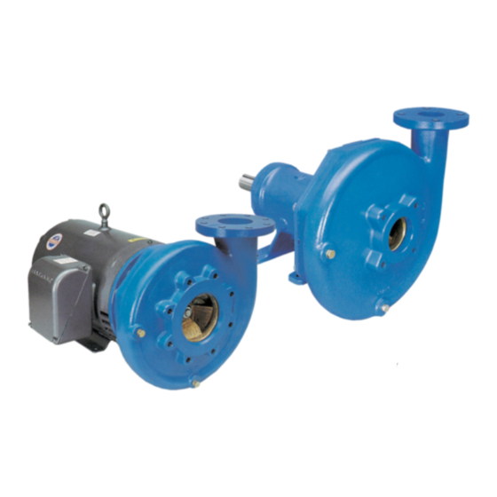
Model
3656/3756
Table of Contents
SUBJECT
Safety Instructions .......................................................... 2
Description and Specifications ........................................ 2
Engineering Data ........................................................... 2
Installation .................................................................... 2
Location .................................................................... 2
Close-Coupled Units .................................................. 2
Frame-Mounted Units ................................................ 3
SAE Engine Driven Pumps .......................................... 3
Coupling Alignment ....................................................... 3
Frame-Mounted Units Only ........................................ 3
Piping ............................................................................ 4
Suction ...................................................................... 4
Discharge ................................................................... 4
Wiring and Grounding ................................................... 4
Rotation ........................................................................ 4
Operation ...................................................................... 4
Maintenance .................................................................. 5
Disassembly ................................................................... 5
Reassembly .................................................................... 6
Packed Box Instructions ................................................. 6
Trouble Shooting ........................................................... 7
Repair Parts ................................................................... 8
Limited Warranty ........................................................ 12
PAGE
Publicidad
Capítulos
Tabla de contenido
Solución de problemas

Manuales relacionados para ITT GOULDS PUMPS 3656


Resumen de contenidos para ITT GOULDS PUMPS 3656
-
Página 1: Tabla De Contenido
Model Installation, Operation and 3656/3756 Maintenance Instructions Table of Contents SUBJECT PAGE Safety Instructions ............2 Description and Specifications ........2 Engineering Data ............2 Installation ..............2 Location ..............2 Close-Coupled Units ..........2 Frame-Mounted Units ..........3 SAE Engine Driven Pumps .......... 3 Coupling Alignment ............ -
Página 2: Safety Instructions
SAFETY INSTRUCTIONS Engineering Data Maximum Liquid Temperature: TO AVOID SERIOUS OR FATAL PERSONAL INJURY 212° F (100° C) – standard seal or packing OR MAJOR PROPERTY DAMAGE, READ AND 250° F (120° C) – Optional high temp. seal FOLLOW ALL SAFETY INSTRUCTIONS IN THE Maximum Working Pressure (table 1): MANUAL AND ON THE PUMP. -
Página 3: Frame-Mounted Units
FRAME-MOUNTED UNITS • For L-Group pumps it is recommended that the pump is supported beneath the two feet cast into the motor adapter • A flat substantial foundation surface MUST be provided to (108). These feet must be bolted to the support. avoid distortion and/or strain when tightening the •... -
Página 4: Piping
• Final alignment is achieved when parallel and angular PIPING – DISCHARGE requirements are satisfied with motor hold-down bolts tight. • Install a check valve suitable to handle the flow, liquids and NOTICE: ALWAYS RECHECK BOTH ALIGNMENTS to prevent backflow. After the check valve, install an AFTER MAKING ANY MECHANICAL appropriately sized gate valve to be used to regulate the ADJUSTMENTS. -
Página 5: Maintenance
SPLASHING OR IMMERSING OPEN FRAME-MOUNTED UNITS WARNING DRIP PROOF MOTORS IN FLUID CAN • Model 3756 S-group has greased for life bearings. CAUSE FIRE, SHOCK, BURNS OR No regreasing is possible or necessary. DEATH. • Model 3756 M or L-group bearing frame and SAE drive bearing frame should be regreased every 2,000 hours or at a three month interval, whichever occurs first. -
Página 6: Reassembly
12. Push out the mechanical seal stationary seat from the 8. Fully and squarely install the rotary assembly of seal seal housing. Discard. against the stationary seat. 13. On units equipped, remove seal housing wear ring (203) NOTICE: REPLACE IMPELLER BOLT AND WASHER if excessively worn. -
Página 7: Trouble Shooting
3. Install the two piece Teflon lantern ring supplied as shown Trouble Shooting Guide in figure 8. Note: two pieces make one ring. Notches on DISCONNECT AND LOCKOUT ring must face each other, but alignment is not necessary. WARNING ELECTRICAL POWER BEFORE ATTEMPTING ANY MAINTENANCE. -
Página 8: Repair Parts
Repair Parts Series 3656/3756 9 10 17 18 Packed Box Arrangement LIQUID END COMPONENTS POWER END COMPONENTS (shown on next page) Item No. Description Material Item No. Description Material Casing Ball bearing (outboard) Steel Impeller Pump shaft Cast iron or bronze Adapter V-ring, deflector BUNA-N... - Página 9 3656/3756 Power Frames 370C 370C S-Group Power Frame M-Group Power Frame 371L 370C 327C 501N 370C L-Group Power Frame SAE Power Frame...
- Página 10 Notes...
- Página 11 Notes...
-
Página 12: Limited Warranty
GOULDS PUMPS LIMITED WARRANTY This warranty applies to all water systems pumps manufactured by Goulds Pumps. Any part or parts found to be defective within the warranty period shall be replaced at no charge to the dealer during the warranty period. The warranty period shall exist for a period of twelve (12) months from date of installation or eighteen (18) months from date of manufacture, whichever period is shorter. - Página 13 Modelo Instrucciones de operación, 3656/3756 instalación y mantenimiento Índice TÓPICO PÁGINA Instrucciones de seguridad ..........14 Descripción y especificaciones ......... 14 Datos de ingeniería ............14 Instalación ..............14 Ubicación..............14 Bombas de acoplamiento corto ........14 Bombas de montaje en bastidor ........15 Bombas accionadas por motor SAE ......
-
Página 14: Instrucciones De Seguridad
INSTRUCCIONES DE SEGURIDAD elementos elastómeros para acoplamiento. Las unidades para montaje en bastidor se pueden acoplar a motores a través de un PARA EVITAR LESIONES PERSONALES GRAVES O acoplamiento espaciador, o pueden ser accionadas por correa. FATALES Y SERIOS DAÑOS MATERIALES, LEA Y SIGA TODAS LAS INSTRUCCIONES DE SEGURIDAD EN EL Datos de ingeniería MANUAL Y EN LA BOMBA. -
Página 15: Bombas De Montaje En Bastidor
más largos para el mayor grosor de soporte. Use bulones SAE BOMBAS DE MONTAJE EN BASTIDOR grado 5, ajustados a la torsión indicada en este manual. • Se DEBE proveer una superficie de base substancial para • Para las bombas del grupo L, se recomienda que estén evitar la distorsión o la tensión al ajustar los bulones de la soportadas debajo de los dos pies fundidos en el adaptador base de montaje. -
Página 16: Tuberías
• Desalineación angular, ejes con línea de centro concéntrica pero no paralela. Coloque el indicador de dial en un rodete y H mín. H mín. haga girar el rodete 360° mientras registra las lecturas en la cara del otro rodete. La alineación angular se alcanza cuando la lectura es 0.005 pulg. -
Página 17: Rotación
SI NO SE LIBERA LA PRESIÓN Y SE Rotación PRECAUCIÓN DRENA EL SISTEMA ANTES DE ATENCIÓN: LA ROTACIÓN INCORRECTA PUEDE INTENTAR TAREAS DE DAÑAR LA BOMBA Y ANULA MANTENIMIENTO, SE PUEDEN LA GARANTÍA. PRODUCIR DAÑOS MATERIALES Y LESIONES PERSONALES, • La rotación correcta es hacia la derecha, en el SENTIDO DE INCLUYENDO LA MUERTE. -
Página 18: Reensamblaje
4. En las unidades de acoplamiento corto, retire el tapón o EXTREMO DEL LÍQUIDO cubierta del extremo del motor para dejar a la vista 1. Inspeccione el eje y limpie toda basura o rebaba. las partes planas o ranuras para el destornillador en ®... -
Página 19: Instrucciones Para La Caja Prensaestopas
16. Vuelva a colocar los pernos de sujeción del motor y el tapón o la cubierta del extremo del motor en las unidades “MANGUITO DIVIDIDO” DE MADERA de acoplamiento corto. 17. Vuelva a colocar los pernos de sujeción del acoplamiento, el espaciador, el protector de acoplamiento y el bastidor en CASQUILLO las unidades montadas en bastidor. -
Página 20: Partes De Repuesto
Partes de repuesto de la Serie 3656/3756 9 10 17 18 Conjunto de la caja prensaestopas COMPONENTES DEL EXTREMO DEL LÍQUIDO COMPONENTES DEL EXTREMO DE POTENCIA (ilustrados en la página siguiente) No. Ítem Descripción Material No. Ítem Descripción Material Carcasa Cojinete de bolas (exterior) Acero Impulsor... - Página 21 Cuadros de fuerza, 3656/3756 370C 370C Cuadro de fuerza, Grupo S Cuadro de fuerza, Grupo M 371L 370C 327C 501N 370C Cuadro de fuerza, Grupo L Cuadro de fuerza, SAE...
- Página 22 Notas...
- Página 23 Notas...
-
Página 24: Garantía Limitada
GARANTÍA LIMITADA DE GOULDS PUMPS Esta garantía es aplicable a todas las bombas para sistemas de agua fabricadas por Goulds Pumps. Toda parte o partes que resulten defectuosas dentro del período de garantía serán reemplazadas, sin cargo para el comerciante, durante dicho período de garantía. Tal período de garantía se extiende por doce (12) meses a partir de la fecha de instalación, o dieciocho (18) meses a partir de la fecha de fabricación, cualquiera que se cumpla primero. - Página 25 Modèles Directives d’installation, 3656 et 3756 d’utilisation et d’entretien Table des matières SUJET PAGE Consignes de sécurité ............. 26 Description et caractéristiques ......... 26 Données techniques ............26 Installation ..............26 Emplacement ............26 Groupes monobloc (pompes sur moteur) ...... 26 Pompes sur palier ............
-
Página 26: Consignes De Sécurité
CONSIGNES DE SÉCURITÉ Les groupes monobloc (pompes sur moteur) sont dotés de moteurs JM ou JP conformes aux normes NEMA, d’un AFIN DE PRÉVENIR LES BLESSURES GRAVES OU adaptateur en C et d’un arbre-rallonge claveté. Les paliers SAE MORTELLES ET LES DOMMAGES MATÉRIELS sont vissés au carter de volant du moteur thermique par IMPORTANTS, LIRE ET SUIVRE TOUTES LES l’intermédiaire d’un support SAE de format n... -
Página 27: Pompes Sur Palier
pattes de l’adaptateur de moteur doivent aussi être INSTALLATION ancrées à cette surface. • S’il s’agit d’une installation horizontale, on peut placer • S’il s’agit d’une installation verticale, protéger le moteur l’orifice de refoulement dans n’importe laquelle des positions contre les intempéries, les éclaboussures, la condensation, etc. permises par les vis (371) du corps de pompe. -
Página 28: Tuyauterie
• Serrer tous les boulons de fixation avant de vérifier • La section de passage de la crépine ou de la tulipe l’alignement. d’aspiration doit être au moins le triple de celle du tuyau d’aspiration. • Lorsqu’un alignement est nécessaire, on doit toujours déplacer •... -
Página 29: Sens De Rotation
OMETTRE LA MISE À LA TERRE Entretien AVERTISSEMENT PERMANENTE DE LA POMPE, DU Tension OMETTRE LE VERROUILLAGE DU MOTEUR ET DES COMMANDES AVERTISSEMENT dangereuse CIRCUIT D’ALIMENTATION AVANT LE BRANCHEMENT À LA ÉLECTRIQUE EN POSITION SOURCE DE COURANT PEUT OUVERTE AVANT D’EFFECTUER CAUSER UN CHOC ÉLECTRIQUE, TOUT TRAVAIL D’ENTRETIEN SUR DES BRÛLURES OU LA MORT. -
Página 30: Remontage
• Pompes sur palier : déposer le carter d’accouplement, la 2. Remplacer les roulements à billes s’ils ont du jeu, s’ils pièce d’écartement de l’accouplement, l’accouplement et ne tournent pas rond ou s’ils sont bruyants. les boulons de fixation du palier. 3. -
Página 31: Presse-Garniture
16. Dans le cas des groupes monobloc, reposer les boulons de fixation, puis l’obturateur ou le couvercle d’extrémité du DOUILLE DE BOIS EN DEUX PIÈCES moteur. 17. S’il s’agit d’une pompe sur palier, reposer l’accouplement, la pièce d’écartement, le carter d’accouplement et les FOULOIR boulons de fixation du palier. -
Página 32: Pièces De Rechange - Séries 3656 Et 3756
Pièces de rechange – séries 3656 et 3756 9 10 17 18 Composants du presse-garniture COMPOSANTS DE LA POMPE COMPOSANTS DES PALIERS (v. page suivante) d’article Description Matériau d’article Description Matériau Corps de pompe Roulement à billes externe Acier Roue Arbre de pompe Fonte ou bronze Adaptateur... - Página 33 Paliers – séries 3656 et 3756 370C 370C Palier du groupe S Palier du groupe M 371L 370C 327C 501N 370C Palier du groupe L Palier SAE...
- Página 34 Notes...
- Página 35 Notes...
-
Página 36: Garantie Limitée De Goulds Pumps
GARANTIE LIMITÉE DE GOULDS PUMPS La présente garantie s’applique à chaque pompe de système d’alimentation en eau fabriquée par Goulds Pumps. Toute pièce se révélant défectueuse sera remplacée sans frais pour le détaillant durant la période de garantie suivante expirant la première : douze (12) mois à compter de la date d’installation ou dix-huit (18) mois à...