Publicidad
Idiomas disponibles
Idiomas disponibles
Enlaces rápidos
Publicidad

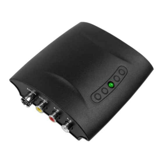
Resumen de contenidos para Illusion MOD-ILL1U
- Página 1 MODULADORES DOMÉSTICOS INDOOR MODULATORS MANUAL DE INSTRUCCIONES INSTRUCTIONS MANUAL...
-
Página 2: Riesgo De Descarga Eléctrica
Precauciones: Introducción a MOD-ILL1U/1V (MODULADORES UHF/VHF PLL) En los canales altos o en grandes instalaciones, podría ser necesario utilizar ● Con los modulador de UHF y VHF podrá distribuir a todos los televisores de un amplificador antes de la mezcla de señal de antena. - Página 3 1a fig 1c CARCACTERÍSTICAS TÉCNICAS: fig 1b MODELO ITEM MOD-ILL1U MOD-ILL1V Sistema PAL-G/B 2042S/2043S ANT a TV 40~1000MHz: 0~5dB D IG I RD D IG I RD Conexión ANT/TV IEC169-2(f)/IEC169-2(m) DIG IRD 2042S/2043S 2042S/2043S Salida RF 470~860MHz Ajus. 111~250MHz Ajus.
- Página 4 7PIN TABLA DE CANALES MOD-ILL1U ON= “1” ,OFF=“0” conmutador estado 7PIN ON= “1” ,OFF=“0” Frecuencia(MHz) conmutador 663.25 × 671.25 Frecuencia(MHz) × 471.25 × 679.25 × 479.25 × 687.25 × 487.25 × 695.25 × 495.25 × 703.25 × 503.25 ×...
- Página 5 Problemas frecuentes y mantenimiento Si encuentra dificultades, consulte la siguiente tabla. TABLA DE CANALES MOD-ILL1V Le guiará a través de los problemas más frecuentes y sus posibles soluciones. estado 7PIN ON= “1” ,OFF=“0” conmutador ▲ Verifique la alimentación Frecuencia(MHz) Sin imagen ▲...
- Página 6 For the correct installation of the modulator watch very carefully the CAUTION ! location of the different connectors and the channel table. In order to choose the output channel, locate by means of your TV-set, a free RF channel at your RISK OF ELECTRIC SHOCK.
- Página 7 1a fig 1c SPECIFICATIONS: fig 1b MODEL ITEM MOD-ILL1U MOD-ILL1V System PAL-G/B 2042S/2043S ANT TO TV 40~1000MHz: 0~5dB D IG I RD D IG I RD ANT/TV Port IEC169-2(f)/IEC169-2(m) DIG IRD 2042S/2043S 2042S/2043S RF Output 470~860MHz Adj. 111~250MHz Adj.
- Página 8 7PIN switch status MOD-ILL1U Channel Table ON= “1” ,OFF=“0” 7PIN switch status Frequency(MHz) ON= “1” ,OFF=“0” 663.25 × Frequency(MHz) 671.25 × 471.25 × 679.25 × 479.25 × 687.25 × 487.25 × 695.25 × 495.25 × 703.25 × 503.25 × 711.25 ×...
-
Página 9: Trouble Shooting Care And Maintenance
Trouble shooting care and maintenance MOD-ILL1V Channel Table If you have some difficulties, consult the following table. It will guide you through the most common problems and their solutions. 7PIN switch status ON= “1” ,OFF=“0” Frequency(MHz) ▲ Check power supply 112.25 ×...