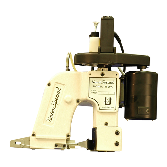
Resumen de contenidos para Union Special 4000 Serie
- Página 1 CATALOG NO. INSTRUCTIONS AND PT0802 ILLUSTRATED PARTS LIST First Edition INSTRUCCIONES Y LISTADO ILUSTRADO DE PARTES STYLES 4000A 4000B CLASS 4000 SERIES PORTABLE BAG CLOSING MACHINES CLASE SERIE 4000 MAQUINA CERRADORA DE SACOS, PORTATIL 02-19-09...
- Página 2 © 2009 PRINTED 2009 IN USA IMPRESO 2009 EN USA INFORMATION SUBJECT TO CHANGE WITHOUT NOTICE INFORMACION SUJETA A CAMBIOS SIN PREVIO AVISO © Union Special Corporation ALL Rights Reserved in All Countries Todos los derechos reservados en todos los paises...
-
Página 3: Safety Rules
Para trabajos de conversiones solamente se tienen que utilizar piezas de recambio originales de Union Special. 9. Any work on the electrical equipment has to be done by electricians or under direction and supervision of Cualquier trabajo en partes eléctricas sólo special skilled personnel. - Página 4 UNION SPE- UNION SPECIAL. CIAL. La aguja recomendada es la aguja tipo D5. Tiene cabo redondo y punta cuadrado largo de Recommended needle is Type D5 .
- Página 5 Fig 1 THREADING DIAGRAM DIAGRAMA DE ENHEBRADO...
- Página 6 Utilice aceite mineral con una viscosidad "SAYBOLT" de 90 a 125 segundos a 100 grados F. Esto es el equivalente a la especificación No. 175 de UNION SPECIAL. El aceite fue drenado del tanque A (fig 2) de la bomba de aceite antes del embarque y el tanque tiene que ser llenado antes de operar la maquina.
- Página 7 MACHINE COMPONENTS COMPONENTE DE LA MAQUINA Fig 3...
-
Página 8: Cambio De La Aguja
ADJUSTMENTS/AJUSTES CHANGING THE NEEDLE Loosen needle bar nut A (Fig. 4) and remove old needle. Locate new D5 (size 200/080) needle and insert needle into needle bar as far as it will go. Turn needle so the the scarf of the needle is facing right and the long groove is facing to the left. -
Página 9: Ajust De La Distancia Del Looper
ADJUSTMENTS CONTINUED/CONTINUACION DE LOS AJUSTES LOOPER GAUGE SETTING Insert a new needle, type and size specified. Looper gauge is 1/32 inch (0.8mm) which is the distance from point of looper ( Fig. 6) to left edge of needle when looper is at extreme backstroke. -
Página 10: Ajuste De La Altura De La Aguja
ADJUSTMENTS CONTINUED/CONTINUACION DE LOS AJUSTES NEEDLE HEIGHT Needle height is correct when the tip of the looper is 1/64 (0.4mm) past the front edge of the needle and the bottom of the looper is even with the top of the needle eye (Fig 8). To adjust, remove the looper cover and needle bar guard, then loosen the needle bar clamping screw (Fig 3) and move needle bar up or down so the top of the needle... -
Página 11: Altura Del Diente Transportador
ADJUSTMENTS CONTINUED/CONTINUACION DE LOS AJUSTE FEED DOG HEIGHT The feed dog should be set 3/32" (2.4mm) above the top of the throat plate at its highest point. To adjust, loosen the feed dog screw (Fig. 3 page 7) and move the feed dog up or down as required. -
Página 12: Belt Tension
ADJUSTMENTS CONTINUED/CONTINUACION DE LOS AJUSTE BELT TENSION The belt must remain slightly flexible with 1/8" to 3/16" (3-4mm) movement (Fig. 12). Apply tension to the belt by opening the motor mount hinge and tightening the 2 screw A (Fig. 13). TENSION DE LA CORREA La correa deberá... - Página 13 TROUBLESHOOTING/PROBLEMAS DE FUNCIONAMIENTO 1) Stitch is too loose. 1) Puntada muy suelta. A) Check the thread tension. A) Revise la tensión de hilo. B) Check the sharpness of the feed B) Revise el filo de los dientes del dog and throat plate teeth. alimentador dentado y de la placa de garganta.
- Página 14 TROUBLESHOOTING/PROBLEMAS DE FUNCIONAMINETO 6) The machine is skipping stitches or does 6) La máquina está saltando puntasdas o no not make a thread chain at the end of the hace una cadena de hilo al final de la bag. bolsa. A) Check thread tension A) Revise la tensión del hilo.
- Página 15 SPARE PARTS/PARTES DE REPUESTO...
- Página 17 HOUSING, NEEDLE LEVER, PRESSER FOOT & THROAT PLATE PARTS Ref. Amt. Part No. Description Req. Housing Assembly (Not available)..............1-1. 4001201-1 Set Screw, #8-32N.C. X 3/16"................1-2. 4001201-2 Spring ........................1-3. 4001201-3 Joint........................1-4. 4001201-4 Oil pipe........................1-5. 4001201-5 Nut....
- Página 19 HOUSING, NEEDLE LEVER, PRESSER FOOT & THROAT PLATE PARTS (CONT'D) Ref. Amt. Part No. Description Req. 4001238 Needle Bar Lever Clamp Assenmbly............4001238A 38A. Needle BarLever Clamp Assembly with Clamp.......... 4001239 39.. Spring......................... 40.. 4001240 Flat Washer....................... 4001241 41.. Screw, #10-32N.F. X 1/2"................42..
- Página 21 MAIN SHAFT & LOOPER ASSEMBLY PARTS Ref. Amt. Part No. Description Req. 52.. 4001452 Mainshaft......................52-1- 4001452-1 Screw......................52-2.. 4001452-2 Oil Felt......................53.. 4001453 Collar, Mainshaft.................... 53-1.. 4001453-1 Screw, #5-40N.C. X 3/8"................54.. 4001454 "O" Ring......................55.. 4001455 Washer, thrust....................Bushing, Mainshaft (rear)................
- Página 23 HANDLE & ELECTRIC DRIVE PARTS Amt. Ref. Description Req. Part No. Oil Pump Assembly..................4 0 0 1 6 0 1 Screw, #8-32N.C. X 1/2" ..................4001603 Spring, Garter ...................... 4001604 Tubing, Oil Pump (4X6X10.5)................4001605 5-1. Tubing, Oil Pump (4X6X20.5)................4001605-1 "O"...
- Página 25 MOTOR PARTS PARTS Amt. Ref. Description Req. Part No. 4002601 Cord ......................4002602 Strain Relief Busings................... 4002603 Case A........................ 4002604 Stator Assembly for 110V................4002604-1 Stator Assembly for 220V................4002605 Ball Bearing....................... 4002607 Armature Assembly for 110V................. 4002607-1 Armature Assembly for 220V................4002608 C-Ring......................
- Página 27 ACCESSORIES Ref. Amt. Part No. Description Req. Accessory Bag .................... 28604R Oil ........................4002403 Spanner Wrench................... 22933105 Screwdriver...................... 4002405 2.0mm Allen Wrench..................WR64 3/32" Allen Wrench..................6-1. W R 7 0 7/64" Allen Wrench..................W R 7 5 5.0mm Allen Wrench..................7-1.

