Tabla de contenido
Publicidad
Idiomas disponibles
Idiomas disponibles
Enlaces rápidos
IB505058ML
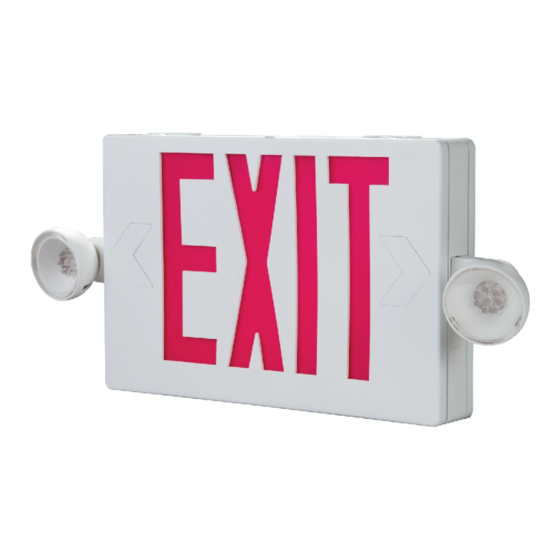
Installation Instructions for the All Pro APC/APCH Combo, and APXH Exit with
Remote Capacity
WARNING
Risk of Fire/Electric Shock
If not qualified, consult an electrician.
Important Safeguards
WHEN USING ELECTRICAL EQUIPMENT, BASIC SAFETY
PRECAUTIONS SHOULD ALWAYS BE OBSERVED INCLUDING
THE FOLLOWING.
1. READ AND FOLLOW ALL SAFETY INSTRUCTIONS
2. Do not use outdoors.
3. Do not use in hazardous locations, or near gas or electric
heaters.
4. Do not let power supply cords touch hot surfaces.
5. Use caution when servicing batteries. Battery acid can
cause burns to skin and eyes. If acid is spilled on skin or in
eyes, flush acid with fresh water and contact a physician
immediately.
6. Do not use this equipment for other than the intended use.
7. Installation is to be performed only by qualified personnel.
8. Install in accordance with National Electric Code and local
regulatory agency requirements.
9. The use of accessory equipment not recommended by the
manufacturer may cause an unsafe condition.
10. Equipment should be mounted in locations and at heights
where it will not readily be subjected to tampering by
unauthorized personnel.
11. SAVE THESE INSTRUCTIONS
DETERMINE CONFIGURATION / ASSEMBLE FIXTURE
1. The APC and APCH Combos can be configured for wall,
ceiling, or end mounting. The mounting method will
determine where the heads can be mounted. The APXH
exits have no heads on the fixture, but can be used to
drive the APWR LED remote heads.
2. Remove the exit sign stencil from the exit frame, to access
the inside of the exit sign.
3. If ceiling or end mounting, remove the appropriate hole
049-211
WARNING
Risk of Electric Shock
Disconnect power at fuse or circuit breaker before
installing or servicing.
plug, and snap in the canopy by sliding it in the keyhole
opening. Place the canopy nose through the mounting
hole until the side of the frame touches the canopy. Lock
the frame onto the canopy by sliding the frame in a
direction parallel to the canopy length toward the narrow
end of the mounting hole. Slide the frame until both snaps
engage the canopy nose preventing any motion back out
of the hole. (see Fig. 1)
4. Select the mounting locations for the heads. Remove the
appropriate hole plug or slot covers. (see Fig. 2)
5. Feed the wires for the heads through the mounting holes,
and then snap the heads into place.
6. Route the wires from the heads to the LED PCB. There are
wire harnesses coming from the circuit board with keyed
connectors that will mate with the connectors from the
heads.
WALL MOUNT INSTALLATION
1. De-energize the circuit at the junction box (J-box) where
the exit sign is to be installed.
2. Drill out the appropriate mounting pattern and the wire
pass hole in the EXIT backplate to fit the J-box being used.
3. Feed the orange, black, and white wires through the center
hole.
4. Connect the J-box wires to the EXIT power supply wires
using the wire nuts provided. Connect the white wire to
neutral. If using 120V, connect the black wire to the hot
lead. If using 277V, connect the orange wire to the hot
lead. Cap the unused lead. Press the wires into the J-box.
5. Secure the EXIT to the wall and/or junction box using
installer supplied hardware.
6. Attach battery leads to PCB.
7. Snap the EXIT stencil onto the frame.
8. Energize AC supply, LED display will come on. LED heads
will illuminate briefly.
EATON
Publicidad
Tabla de contenido

Manuales relacionados para Eaton All Pro APC

Resumen de contenidos para Eaton All Pro APC
- Página 1 EATON IB505058ML 049-211 Installation Instructions for the All Pro APC/APCH Combo, and APXH Exit with Remote Capacity WARNING WARNING Risk of Fire/Electric Shock Risk of Electric Shock If not qualified, consult an electrician. Disconnect power at fuse or circuit breaker before installing or servicing.
-
Página 2: Troubleshooting Guide
Installation Instructions for the All Pro APC/APCH Combo, and APXH Exit with Remote Capacity Figure 1 4. Feed the orange, black, and white wires through the canopy nose. Mounting Plate 5. Feed the wires from the J-box through the steel mounting... - Página 3 Installation Instructions for the All Pro APC/APCH Combo, and APXH Exit with Remote Capacity SCHEMATICS APC Models available with two LED lamp heads. APCH High Power Models available with up to 4 LED lamp heads. LED LAMP LED LAMP 2ND BATTERY FOR APCH...
-
Página 4: Mesures De Sécurité Importantes
EATON IB505058ML 049-211 Instructions d’installation pour la combinaison APC/APCH All Pro, et l’enseigne de sortie APXH avec capacité de commande à distance AVERTISSEMENT AVERTISSEMENT Risque d’incendie et de choc électrique Risque de choc électrique Contacter un électricien si vous n’êtes pas qualifié. -
Página 5: Installation Au Plafond Ou En Extrémité
Instructions d’installation pour la combinaison APC/APCH All Pro, et l’enseigne de sortie APXH avec capac- ité de commande à distance INSTALLATION AU PLAFOND OU EN EXTRÉMITÉ 6. Raccordez les fils de la batterie à la carte de circuit imprimé. 7. Enclenchez la découpe de l’enseigne EXIT (Issue) sur le 1. -
Página 6: Guide De Dépannage
FIL NOIR - VERS LE 120 V D'ALIMENTATION FIL BLANC - VERS LE NEUTRE ÉLECTRIQUE Garanties et limitation de responsabilité Veuillez consulter le site www.eaton.com/WarrantyTerms pour obtenir les conditions générales. Eaton © 2017 Eaton 1121 Highway 74 South All Rights Reserved Eaton is a registered trademark. -
Página 7: Medidas Importantes De Seguridad
EATON IB505058ML 049-211 Instrucciones de instalación para todos los juegos Pro APC/APCH y la salida APXH con capacidad remota ADVERTENCIA ADVERTENCIA Riesgo de incendio o electrocución Riesgo de descarga eléctrica Si no está calificado, consulte con un electricista. Antes de instalar o dar mantenimiento desconecte el suministro eléctrico en la caja de fusibles o interruptores. -
Página 8: Instalación En El Techo O En Su Costado
Instrucciones de instalación para todos los juegos Pro APC/APCH y la salida APXH con capacidad remota 4. Conecte los cables de la caja eléctrica a los cables de INSTALACIÓN EN EL TECHO O EN SU COSTADO suministro de la señal de SALIDA usando las tuercas de 1. -
Página 9: Mantenimiento
Installation Instructions for the All Pro APC/APCH Combo, and APXH Exit with Remote Capacity MANTENIMIENTO GUÍA DE LOCALIZACIÓN Y SOLUCIÓN DE AVERÍAS No se requiere mantenimiento. Sin embargo, le recomendamos Si los cabezales LED o el LED indicador de recarga no se que pruebe el equipo regularmente según los códigos locales.