Tabla de contenido
Publicidad
Idiomas disponibles
Idiomas disponibles
Enlaces rápidos
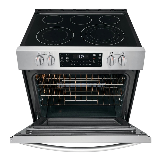
INSTALLATION INSTRUCTIONS
FRONT CONTROL FREESTANDING ELECTRIC RANGE
IMPORTANT: SAVE FOR LOCAL ELECTRICAL INSPECTOR'S USE.
READ AND SAVE THESE INSTRUCTIONS FOR FUTURE REFERENCE.
United States
IMPORTANT SAFETY INSTRUCTIONS
If the information in this manual is not followed
exactly, a fire or electrical shock may result causing property
damage, personal injury or death.
Important Notes to the Installer:
•
Read all instructions contained in these installation
instructions before installing range.
Remove all packing material from the oven
•
compartments before connecting the gas & electrical
supply to the range.
Observe all governing codes and ordinances.
•
Be sure to leave these instructions with the
•
consumer.
Important Notes to the Consumer:
Keep these instructions with your owner's guide for future
reference.
As when using any appliance generating heat, there
•
are certain safety precautions you should follow.
These are listed in the Use & Care Guide, read it
carefully.
Be sure your range is installed and grounded properly
•
by a qualified installer or service technician.
Make sure the wall coverings around the range can
•
withstand the heat generated by the range.
To eliminate the need to reach over the surface
•
elements, cabinet storage space above the elements
should be avoided.
INSTALLATION AND SERVICE MUST BE
PERFORMED BY A QUALIFIED INSTALLER.
FOR YOUR SAFETY: Do not store or use gasoline
or other flammable vapors and liquids in the vicinity of this or
any other appliance.
• A child or adult can tip the
range and be killed.
• Verify the anti-tip device has
been installed to floor or wall.
• Ensure the anti-tip device is re-engaged to floor
or wall when the range is moved.
• Do not operate the range without the anti-tip
device in place and engaged.
• Failure to follow these instructions can result in
death or serious burns to children and adults.
To check if the anti-tip bracket is installed properly, use
both arms to grasp the rear edge of the range back.
Carefully attempt to tilt range forward. When properly
installed, the range should not tilt forward.
Refer to the anti-tip bracket installation instructions
supplied with your range for proper installation.
1
Tip Over Hazard
Range
leveling leg
P/N 809127105 (1901) Rev. C
English – pages 1-8
Spanish - pages 9-16
Anti-tip
bracket
Publicidad
Tabla de contenido

Manuales relacionados para Frigidaire FGEH3047VFA


Resumen de contenidos para Frigidaire FGEH3047VFA
- Página 1 INSTALLATION INSTRUCTIONS FRONT CONTROL FREESTANDING ELECTRIC RANGE INSTALLATION AND SERVICE MUST BE PERFORMED BY A QUALIFIED INSTALLER. IMPORTANT: SAVE FOR LOCAL ELECTRICAL INSPECTOR'S USE. READ AND SAVE THESE INSTRUCTIONS FOR FUTURE REFERENCE. FOR YOUR SAFETY: Do not store or use gasoline United States or other flammable vapors and liquids in the vicinity of this or any other appliance.
- Página 2 30” ELECTRIC FRONT CONTROL FREESTANDING INSTALLATION INSTRUCTIONS 1. Clearances and Dimensions a. Provide adequate clearances between the range and adjacent combustible surfaces. b. Location—Check location where the range will be installed. Check for proper electrical supply and the stability of floor. c.
-
Página 3: Tools You Will Need
30” ELECTRIC FRONT CONTROL FREESTANDING INSTALLATION INSTRUCTIONS 2. Tools You Will Need If rear of range is further than 1-1/4" (32 mm) from the wall when installed, attach bracket to the floor. For floor mount, locate the bracket by placing back edge of the For leveling legs and Anti-Tip Bracket: template where the rear of the range will be located. -
Página 4: Electrical Connection Requirements
30” ELECTRIC FRONT CONTROL FREESTANDING INSTALLATION INSTRUCTIONS C. Level and Position Range - Level range by adjusting the Models requiring power supply cord (4) leveling legs with a wrench. Note: Aminimum clearance of 1/8” (3 mm) is required between the bottom of the RISK OF FIRE OR ELECTRICAL SHOCK MAY OCCUR IF range and the leveling leg to allow room for the bracket. - Página 5 30” ELECTRIC FRONT CONTROL FREESTANDING INSTALLATION INSTRUCTIONS Fig. 10 NOTE: Internal white wire not present on all models. Fig. 12 5B. POWER CORD CONNECTIONS (3-Wire Connection Instructions For existing installations ONLY - Refer to Fig. 13). Fig. 11 1. Follow the manufacturer’s installation instructions supplied with the strain relief and install (Also see Figs.
- Página 6 30” ELECTRIC FRONT CONTROL FREESTANDING INSTALLATION INSTRUCTIONS 6. Carefully Slide Range Into Grounding Instructions (3-Wire Connections only) Final Location A ground strap is installed on this range which connects Be sure to provide all the adequate clearances and dimensions the center terminal of the terminal block (Neutral) to the shown in Figs.
- Página 7 30” ELECTRIC FRONT CONTROL FREESTANDING INSTALLATION INSTRUCTIONS 7. Install filler trim kit 8. Door Handle Mounting In- structions (some models) Note: Installation of the filler trim kit is not required. Disconnect electrical power to range before 1. Remove handles from carton and any other protective beginning installation.
-
Página 8: Model And Serial Number Location
30” ELECTRIC FRONT CONTROL FREESTANDING INSTALLATION INSTRUCTIONS 9. Model and Serial Number Some models have a cool-air intake vent on the rear of the appliance. Do not block or obstruct this vent. Location The serial plate is located on the right-hand surface of the oven front frame at the storage or warmer drawer;... -
Página 9: Para Su Seguridad
INSTRUCCIONES DE INSTALACION LA ESTUFA ELECTRICA DE 30” LA INSTALACION Y EL SERVICIO DEBEN SER EFECTUADOS POR UN INSTALADOR CALIFICADO. IMPORTANTE: CONSERVE ESTAS INSTRUCCIONES PARA USO DEL INSPECTOR LOCAL DE ELECTRICIDAD. LEA Y CONSERVE ESTAS INSTRUCCIONES PARA REFERENCIA FUTURA. Estados Unidos PARA SU SEGURIDAD: No almacene ni use gasolina u otros vapores y líquidos inflamables cerca de este o cualquier otro electrodoméstico. - Página 10 INSTRUCCIONES DE INSTALACION PARA LA ESTUFA ELECTRICA DE 30” 1. Espacios y dimensiones a. Proporcione espacios adecuados entre la estufa y las superficies combustibles adyacentes. b. Ubicación—Examine el lugar en el cual va a ser instalada la estufa. Determine la existencia de suministro eléctrico adecuado y la estabilidad del piso.
-
Página 11: Herramientas Que Va A Necesitar
INSTRUCCIONES DE INSTALACION PARA LA ESTUFA ELECTRICA DE 30” 2. Herramientas que va a pared. Si la parte trasera de la estufa está a más de 1-1/4” de la pared cuando ya está instalada, instale el soporte necesitar en el piso. Para el montaje en el piso, ubique el soporte colocando el borde trasero de la plantilla donde quedará... -
Página 12: Requisitos De Conexión Eléctrica
INSTRUCCIONES DE INSTALACION PARA LA ESTUFA ELECTRICA DE 30” Modelos que requieren Juego de C. Nivele y ubique la estufa - Nivele la estufa ajustando los cuatro (4) tornillos niveladores con una llave. Nota: Se Cordón para el Suministro de Energía debe dejar un espacio libre mínimo de 1/8”... - Página 13 INSTRUCCIONES DE INSTALACION PARA LA ESTUFA ELECTRICA DE 30” Conexión Tetrafilar Tabla del Tamaño de la Abertura de Conexión de la Estufa Conexiones instaladas en la fábrica (NO AFLOJAR) Informació sobre la potencia nominal en amperios del Juego de Cable de Alimentación.
-
Página 14: Instrucciones Para La Puesta A Tierra (Para Conexiones Trifilares Solamente)
INSTRUCCIONES DE INSTALACION PARA LA ESTUFA ELECTRICA DE 30” 6. DESLICE CON CUIDADO LA Instrucciones para la Puesta a Tierra (para conexiones trifilares solamente) ESTUFA HASTA SU LUGAR Esta estufa tiene instalada una cinta de conexión a tierra DEFINITIVO que conecta el borne central del tablero de bornes (neutro) al chasis de la estufa. -
Página 15: Instalar Kit De Ajuste De Relleno
INSTRUCCIONES DE INSTALACION PARA LA ESTUFA ELECTRICA DE 30” 7. Instalar kit de ajuste de 8. Instrucciones de montaje de relleno las asas de puerta Nota: no es necesario instalar el kit de acabado de relleno. Extraiga el asa de la caja y retire el envoltorio de protección. Corte la alimentación eléctrica de la estufa Coloque los capuchones del asa sobre los pernos de tope entes de instalar. -
Página 16: Ubicación Del Modelo Y Número De Serie
INSTRUCCIONES DE INSTALACION PARA LA ESTUFA ELECTRICA DE 30” 7. Ubicación del modelo y Algunos modelos tienen un respiradero de admisión de aire frío en la parte posterior del aparato. No número de serie bloquee u obstruya esta ventilación. La placa de serie está ubicada en la superficie derecha del marco frontal del horno en el cajón de almacenamiento o calentador;...