Tabla de contenido
Solución de problemas

Manuales relacionados para Sears BBQ-RPO 146.47468610

Resumen de contenidos para Sears BBQ-RPO 146.47468610
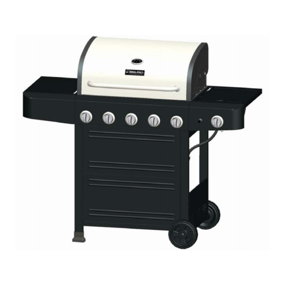
- Página 1 OWNER’S MANUAL BBQ Pro 5 Burners gas grill with Stainless Steel lid Product code: 47468 / 0-02236025-9 Item: 146.47468610 UPC code: 182995001771 Date of purchase:...
-
Página 2: Important
If you have questions or need assistance during assembly, convenient place for future reference. please call 1-888-287-0735. You will be speaking to a representative of the grill manufacturer and not a Sears Safety Symbols employee. To order new parts call Sears at The symbols and boxes shown below explain what each heading 1-800-4-MY-HOME®. -
Página 3: Tabla De Contenido
Fast help by phone - we call it Rapid Resolution Sears Installation Service phone support from a Sears representative. Think of For Sears professional installation of home appliances, garage us as a “talking owner’s manual.”... - Página 4 LP Cylinder USE AND CARE • The LP cylinder used with your grill must meet the following requirements: DANGER • Use LP cylinders only with these required measurements: 12" (30.5cm) (diameter) x 18" (45.7 cm) (tall) with 20 lb. (9 kg.) Capacity maximum.
-
Página 5: For Your Safety
LP Tank Exchange Connecting Regulator To The LP Tank • Many retailers that sell grills offer you the option of replacing 1. LP tank must be properly secured onto grill. (Refer to your empty LP tank through an exchange service. Use only those assembly section.) reputable exchange companies that inspect, precision fill, test 2. - Página 6 3. Completely open LP tank valve by turning OPD hand wheel counterclockwise. If you hear a rushing sound, turn gas off immediately. There is a major leak at the connection. Correct before proceeding by calling Sears for replacement parts at 1-800-4-MY-HOME®. Hold coupling nut and regulator 4 .Brush soapy solution onto areas where bubbles are shown in...
-
Página 7: Safety Tips
Safety Tips WARNING ▲ Before opening LP cylinder valve, check the coupling nut for tightness. ▲ When grill is not in use, turn off all control knobs and LP cylinder For Safe Use of Your Grill and to Avoid Serious valve. -
Página 8: Use And Care
Burner Flame Check WARNING • Remove cooking grates and heat diffusers. Light burners, turn knobs from HI to LO. You should see a smaller flame in LO position than seen on HI. Perform burner flame check Turn controls and gas source or tank OFF when not on sideburner, also. -
Página 9: Storing Your Grill
Cleaning the Burner Assembly WARNING CAUTION Follow these instructions to clean and/or replace parts of burner assembly or if you have trouble igniting grill. 1. Turn gas off at control knobs and LP cylinder. SPIDER ALERT! SPIDER ALERT! SPIDER ALERT! 2. -
Página 10: Indirect Cooking
Indirect Cooking Food Safety Poultry and large cuts of meat cook slowly to perfection on the grill Food safety is a very important part of enjoying the outdoor by indirect heat. Place food over unlit burner(s); the heat from lit cooking experience. -
Página 11: Parts List
PARTS LIST PARTS LIST Description Key Description Key Description Part Number Part Number HEAT DIFFUSERS 52200004 D06 Side Burner 52200053 COOKING GRATE A02 Temperature Gauge 52200015 D07 Right Side Shelf 52200047 SWING AWAY GRATE A03 Logo 52200200 D08 Electronic Ignition Module 40800122 CLIP, F/ GREASE CUP A04 Rotate Rod, Lid... -
Página 12: Parts Diagram
PARTS DIAGRAM B07 B06 B05 12 • 146.47468610... -
Página 13: Before Assembly
BEFORE ASSEMBLY NOTICE: Once you have unpacked the grill according to the STOP SHEET instructions, check all grill parts against the pictures on this and the following two pages. If any parts are missing or damaged, call 1-888-287-0735 146.47468610 • 13... - Página 14 BEFORE ASSEMBLY 14 • 146.47468610...
- Página 15 BEFORE ASSEMBLY 146.47468610 • 15...
-
Página 16: Assembly
ASSEMBLY CAREFULLY READ AND PERFORM ALL ASSEMBLY INSTRUCTIONS ON THE FOLLOWING PAGES. Tools Required: Adjustable wrench (not provided) Screwdriver (not provided) 7/16” Combination wrench (not provided) The following hardware is provided in blister pack for convenient use. M4X10 screw AAA Battery Qty: 58 pcs Qty: 1 pc M6X13 screw... - Página 17 Left Frame Install (4)M4×10 Screws as shown to the leg marked “5A”. Do not fully tighten the screws at this □ time. (A) □ Attach one end of Side Upper Rail to the leg, tighten the screws and attach with another (1)M4× 10 Screw.(C) □...
- Página 18 Right Frame □ Install (4)M4×10 Screws as shown to the leg marked “5C”. Do not fully tighten the screws at this time. (A) □ Attach one end of Side Upper Rail to the leg, tighten the screws and attach with another (1)M4×10 Screw.(C) □...
- Página 19 Bottom Shelf □ Install (4)M4×10 Screws as shown to Right Frame. Do not fully tighten the screws at this time. (A) □ Attach Bottom Shelf to Right Leg Frame with (3)M4×10 Screws. Do not tighten these screws. (A) □ Install (4)M4×10 Screws as shown to Left Frame. Do not fully tighten the screws at this time. (B) □...
-
Página 20: Front Panel
Front Panel □ Attach the two Front Panels together with (1)M4×10 Screws as shown. (a) □ Attach the front panels to the cart, leave the top 2 screws loose, and tighten all remaining screws. □ Attach the Right Drip Tray support to the Right Frame, fully tighten the screw,(b) tighten another end of the Support Bar to the frame with (2)M4×10 Screws as shown.(c) □Attach the Left Drip Tray Support to the Left Frame, fully tighten the screw, tighten another end of the Left Drip Tray Support Bar to the frame with (2)M4×10 Screws as shown. - Página 21 Wheels to Cart □ Turn cart upside down, attach remaining screws to the Bottom Shelf and Four Legs with (4)M6×13 Screws as shown.(A) □Tap both Leg Extenders onto Left Leg.(B) □Remove washer nut & hitch pin from axle rod Insert Axle Rod through Wheels and Right Leg Frame, Reattach with washer, nut and hitch pin.(C) □...
- Página 22 Grill Head to Cart □ This step requires two people to lift and position grill head on to cart. □ Remove the tie wraps and packaging material from regulator hose, side burner valve and igniter wire. Pull hose and igniter wire out to side of grill head. □...
- Página 23 Temperature Gauge Temperature Gauge through Lid and tighten with the Wing Nut. □ Place the Left Side Shelf (1) □ Install the (2)M6×13 Screws on the left of Firebox. Do not fully tighten the screws. □ Place on the Left Side Shelf bracket and pull to its position. M6X13 screw Qty: 2 pcs 146.47468610 •...
- Página 24 NOTES Left Side Shelf (2) □ Open the Lid, attach the shelf to Firebox as follows: - From inside to outside of firebox with (2)M6×13 Screws and (2)M6 compression washers.(A) □ Align the Side Fascia and Control Panel, attach them from outside to inside of Firebox with (1)M4× 10 Screws.
- Página 25 Right Side Shelf (1) □ Install the (2)M6×13 Screws on the Right of Firebox. Do not fully tighten the screws. □ Place on the Right Side Shelf bracket and pull to its position. M6X13 screw Qty: 2 pcs 146.47468610 • 25...
- Página 26 Right Side Shelf (2) □ Open the Lid, attach the shelf to Firebox as follows: - From inside to outside of firebox with (2)M6×13 Screws and (2)M6 compression washers.(A) □ Align the Side Fascia and Control Panel, attach them from outside to inside of Firebox with (1)M4× 10 Screws.
- Página 27 Sideburner □ Loosen side burner in side shelf. (B ). To loosen, unscrew and remove two front screws and washers holding side burner in place. (A). Note: Do not loosen electrode screw. □ Remove the 2 pre-installed screws from the valve stem and set them aside. (C) □...
- Página 28 28 • 146.47468610...
- Página 29 Heat Diffusers, Cooking Grates and Warming Rack □ Place Heat Diffusers over burners. Diffusers will fit in firebox in either direction. Fit tabs in firebox front through slots in Diffusers tips, Fit diffusers tips between tabs in Firebox Rear. □ Place Cooking Grates onto grate rests at front and rear of Firebox. □...
- Página 30 Drip Tray, Drip Cup and LP Tank □ Attach Back Rail to the Cart and Grill Head with (4)M4×10 Screws as shown.(A) □ Remove the cotter key and retention pin from the hose bracket on cart right leg. Insert hose into bracket and replace cotter and pin.
-
Página 31: Troubleshooting
EMERGENCIES: If a gas leak cannot be stopped, or a fire occurs due to gas leakage, call the fire department. Problem Possible Cause Prevention/Solution Gas leaking from •Turn off gas at LP cylinder or at source on natural gas systems. •... - Página 32 Troubleshooting (continued) Prevention/Solution Problem Possible Cause Prevention/Solution Burner(s) will not light ELECTRONIC IGNITION: • See Section I of Electronic Ignition System. using igniter. • No spark, no ignition noise. (See Electronic • See Section II of Electronic Ignition System. Ignition •...
- Página 33 Troubleshooting - Electronic Ignition Prevention/Solution Problem Possible Cause Check Item Preventio • Battery not installed SECTION I • Check battery orientation. • Install battery (make sure that “+” and “-” properly. No sparks appear at connectors are oriented correctly, with “+” end any electrodes when up and “-”...
- Página 34 MANUAL DE PROPIETARIO BBQ Pro 5 quemadores parrilla de gas con tapa de acero inoxidable Código de producto: 47468 / 0-02236025-9 Item: 146.47468610 Código de UPC: 182995001771 Fecha de compra:...
-
Página 35: Inscripción Del Producto
1-888-287-0735. Hablará con un representante del NOTA A LOS CONSUMIDORES: Deja este manual del usuario en fabricante de la parrilla, no con un empleado de Sears. Para un lugar conveniente para futura referencia. pedir piezas nuevas, llame a Sears al 1-800-4-MY-HOME®. -
Página 36: Índice De Materias
Servicio ilimitado sin cargo por piezas ni por mano de obra paratodas las reparaciones amparadas por el contrato Sears Roebuck and Co. Cambio del producto, por un valor de hasta $1500, si no sepuede reparar su producto amparado por el contrato... -
Página 37: Uos Y Mantenimiento
UOS Y MANTENIMIENTO Tanque de gas propano • El tanque de gas que use con su parrilla debe cumplir los PELIGRO siguientes requisitos: • Use únicamente tanques de gas que tengan las siguientes medidas obligatorias: 12" (30.5 cm) (diámetro) x 18" (45.7 •... -
Página 38: Cambio Del Tanque De Gas
Cambio del tanque de gas Como conectar el regulador al tanque de gas propano • Muchos comerciantes minoristas que venden parrillas, le 1. El tanque de gas debe quedar bien fijado a la parrilla. (Lea la ofrecen la opción de cambiar su tanque de gas vacío mediante sección de ensamblado.) un servicio de recambio. -
Página 39: Prueba Para Detectar Fugas De Las Válvulas, Las Mangueras Y El Regulador
Prueba para detectar fugas de las válvulas, las mangueras y el regulador 1. Gire todas las perillas de control de la parrilla a la posición deAPAGADO. 2. Cerciórese de que el regulador esté bien conectado al tanque de gas. 3. Abra por completo la válvula del tanque, girando la manilla en sonido sentido contrario a las agujas del reloj. -
Página 40: Para Usar Su Parrilla En Forma Segura Y Para Evitar Lesiones Graves
Consejos de seguridad ADVERTENCIA ▲ Verifique que la tuerca de unión esté bien apretada antes de abrir la válvula del tanque de gas. ▲ Cuando no use la parrilla, cierre todas las perillas de control Para usar su parrilla en forma segura y para evitar y la válvula del tanque de gas. -
Página 41: Encendido Con Fósforos
Control de la llama del quemador ADVERTENCIA • Retire las parrillas de cocción y los reguladores de llama. Encienda los quemadores y gire las perillas, de la graduación ALTA (HI) a la graduación BAJA (LO). Deberá ver una llama más reducida en la Gire los controles y la fuente de gas o OFF tanque cuando graduación baja que en la graduación alta. -
Página 42: Cómo Limpiar La Unidad Del Quemador
Cómo limpiar la unidad del quemador CAUTION Siga estas instrucciones para limpiar o cambiar piezas de la unidad del quemador, o si tiene problemas para encender la parrilla. 1. Cierre el paso de gas en las perillas de control y desde el tanque de gas. -
Página 43: Cocción Indirecta
Cocción indirecta Cocción: Cocine bien las carnes y las piezas de ave, para matar las bacterias. Use un termómetro para verificar que los alimentos Las aves y los cortes grandes de carne se cocinan lentamente a la alcancen la temperatura interna adecuada. perfección en la parrilla por calor indirecto. -
Página 44: Lista De Piezas
LISTA DE PIEZAS Cant Cant Clave Descripción Pieza No. Clave Descripción Pieza No. Description Tapa 52200004 quemador lateral 52200053 Indicador de temperatura 52200015 Right Side Shelf 52200047 Módulo encendido Logo 52200200 40800122 electrónico Girar Rod, Tapa 50300207 Fascia, Right Side Shelf 52200049 Caucho de silicona parachoques, 40700103... -
Página 45: Diagrama De Partes
DIAGRAMA DE PARTES B07 B06 B05 146.47468610 • 45... -
Página 46: Antes De La Asamblea
ANTES DE LA ASAMBLEA Aviso: Una vez desempaquetado la parrilla según las instrucciones de detener la hoja, revise que todo parrilla partes contra los cuadros sobre ésta y las siguientes dos páginas. Si alguna pieza está dañada o falta, llame al 1-888-287-0735 46 •... - Página 47 ANTES DE LA ASAMBLEA 146.47468610 • 47...
- Página 48 ANTES DE LA ASAMBLEA 48 • 146.47468610...
- Página 49 ASSEMBLY CAREFULLY READ AND PERFORM ALL ASSEMBLY INSTRUCTIONS ON THE FOLLOWING PAGES. Tools Required: Adjustable wrench (not provided) Screwdriver (not provided) 7/16” Combination wrench (not provided) The following hardware is provided in blister pack for convenient use. M4X10 screw AAA Battery Qty: 58 pcs Qty: 1 pc M6X13 screw...
-
Página 50: Cuadro Izquierdo
Cuadro izquierdo Instalar (4) M4 × 10 Tornillos como se muestra a la pata marcada "5A". No apriete los tornillos □ en este momento. (A) □ Conecte un extremo de la parte superior del carril a la pierna, apriete los tornillos y conectar con otro (1) M4 ×... - Página 51 cuadro derecho □ Instalar (4) M4 × 10 Tornillos como se muestra a la pata marcada "5C". No apriete los tornillos en este momento. (A) □ Conecte un extremo de la parte superior del carril a la pierna, apriete los tornillos y conectar con otro (1) M4 ×...
- Página 52 Bottom Shelf Instalar (4) M4 × 10 Tornillos como se muestra a la derecha del marco. No apriete los tornillos en □ este momento. (A) □ Adjuntar estante inferior al cuadro derecho Pierna con (3) M4 × 10 Tornillos. No apriete los tornillos.
-
Página 53: Panel Frontal
Panel frontal Conecte los dos paneles frontales junto con (1) M4 × 10 Tornillos como se muestra. (a) □ □ Coloque los paneles frontales a la compra, deje los 2 tornillos superiores aflojar y apretar todos los tornillos conservan. □ Fije el soporte de la bandeja de goteo Derecho a la Armadura Derecha, apriete completamente el tornillo, apriete el otro extremo de la barra de soporte a la estructura con (2) M4 ×... - Página 54 Ruedas a la Cesta Gire a la cesta boca abajo, coloque los tornillos restantes del estante inferior y cuatro patas con (4) □ M6 × 13 Tornillos como se muestra. (A) □ Toque en tanto la pierna extensores en el pie derecho de la pierna. (B) □...
- Página 55 Grill Cabeza a la Cesta □Este paso requiere de dos personas para levantar la cabeza y la posición en la parrilla de la compra. □ Retire las abrazaderas y material de embalaje de la manguera del regulador, válvula del quemador lateral y el cable de encendido. Tire de la manguera y el cable de encendido a lado de la cabeza de la parrilla.
-
Página 56: Indicador De Temperature
Indicador de temperature □Coloque el indicador de temperatura a través de la tapa y apriete con la Tuerca de mariposa. Left Side Shelf (1) □ Instale el (2) M6 × 13 Tornillos de la izquierda del Firebox. No apriete completamente los tornillos. □... - Página 57 NOTES Left Side Shelf (2) □ Abra la tapa, coloque la plataforma de la caja de fuegos de la siguiente manera: - Desde el interior al exterior de la cámara de combustión con (2) M6 × 13 Tornillos y (2) arandelas de compresión M6 (A).
- Página 58 Right Side Shelf (1) □ Instale el (2) M6 × 13 Tornillos sobre el derecho de Firebox. No apriete completamente los tornillos. □ Coloque en el soporte del lado derecho del estante y saque a su posición. M6X13 Tornillos Qty: 2 58 •...
- Página 59 Right Side Shelf (2) □ Abra la tapa, coloque la plataforma de la caja de fuegos de la siguiente manera: - Desde el interior al exterior de la cámara de combustión con (2) M6 × 13 Tornillos y (2) arandelas de compresión M6 (A).
- Página 60 quemador lateral □Afloje quemador lateral en la repisa lateral. (B). Para aflojar, desenroscar y quitar dos tornillos delanteros y arandelas que sostienen quemador lateral en su lugar. (A). Nota: No afloje el tornillo del electrodo. □ Retire los 2 tornillos preinstalados del vástago de la válvula y la puso a un lado. (C) □...
- Página 61 146.47468610 • 61...
- Página 62 Los difusores de calor, parrillas de cocción y calentamiento rack □ Coloca difusores de calor sobre los quemadores. Los difusores se ajusta en la cámara de combustión en cualquier dirección. Lengüetas de ajuste frente cámara de combustión a través de ranuras en consejos Difusores, difusores consejos ajuste entre pestañas en Firebox posterior.
-
Página 63: Bandeja De Goteo, Goteo De La Copa Y El Tanque De Gas
Bandeja de goteo, goteo de la Copa y el tanque de gas □ Adjuntar Volver Rail a la Cesta and Grill Cabeza con (4) M4 × 10 Tornillos como se muestra. (A) □ Retire la llave de chaveta y el pasador de retención del soporte de la manguera en la cesta de la pierna derecha. -
Página 64: Emergencias
EMERGENCIAS: Si no se puede detener una fuga de gas, o si ocurre un incendio debido a una fuga de gas, llame a los bomberos. Emergencias Causas probables Medidas de prevención / solución • Cierre el gas en el cilindro o en la fuente de los sistemas de gas natural. •... -
Página 65: Resolucion De Problemas (Continuacion)
Resolucion de problemas (continuacion) Problema Causas probables Medidas de prevención / solución • Limpie el cable y el electrodo con alcohol de frotar y un hisopo El quemador o los • El cable o el electrodo está cubierto con limpio. quemadores no se restos de comida. -
Página 66: Resolución De Problemas - Encendido Electrónico
Resolución de problemas – Encendido electrónico Medidas de prevención / solución Problema (encendido) Causas probables Procedimiento de revisión Preventio Causas probables • Revise la orientación de la • Instale la pila (verifique que los polos “+” y “–” • La pila no está SECCIÓN I pila.