Tabla de contenido
Solución de problemas

Manuales relacionados para Westinghouse Ripley


Resumen de contenidos para Westinghouse Ripley
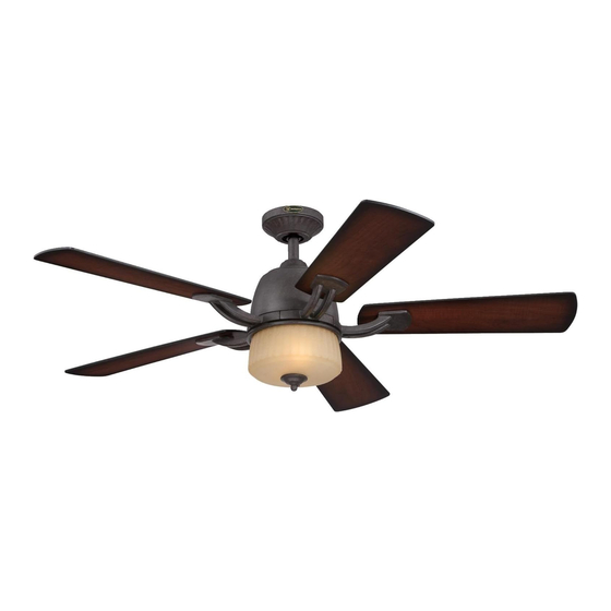
- Página 1 ETL-ES-Ripley-WH15 Owner's Manual Manual del usuariO Ripley Please write model number here for future reference: / Por favor, incluya el número del modelo aquí para futura referencia: net weight: 19.80 lBs Peso neto: 9.0 KGs...
-
Página 2: Safety Tips
ETL-ES-Ripley-WH15 SafETy TiPS OBSERVE THE fOLLOWiNG: REaD aND SaVE THESE iNSTRUCTiONS WaRNiNG: TO REDUCE THE RiSK Of fiRE, ELECTRiC SHOCK, OR PERSONaL iNJURy, MOUNT TO OUTLET BOX MaRKED 'aCCEPTaBLE fOR faN SUPPORT Of 15.9 KG (35 LBS) OR LESS' aND USE MOUNTiNG SCREWS PROViDED WiTH THE OUTLET BOX aND/OR SUPPORT DiRECTLy fROM BUiLDiNG STRUCTURE. MOST OUTLET BOXES COMMONLy USED fOR THE SUPPORT Of LUMiNaRiES aRE NOT aCCEPTaBLE fOR faN SUPPORT aND May NEED TO BE REPLaCED. -
Página 3: Consejos De Seguridad
ETL-ES-Ripley-WH15 CONSEJOS DE SEGURiDaD HaGa LO SiGUiENTE: LEa y GUaRDE ESTaS iNSTRUCCiONES aDVERTENCia: PaRa REDUCiR EL RiESGO DE iNCENDiO, DESCaRGa ELÉCTRiCa O HERiDaS GRaVES PERSONaLES, MONTE EN UNa CaJa DE EMBUTiR ROTULaDa “aDECUaDa PaRa VENTiLaDORES DE 15,9 KG (35 LB) O MENOS” UTiLiZaNDO LOS TORNiLLOS DE MONTaJE iNCLUiDOS CON La CaJa DE EMBUTiR y/O MONTE DiRECTaMENTE EN La ESTRUCTURa DEL EDifiCiO La MayORÍa DE LaS CaJaS DE EMBUTiR UTiLiZaDaS .NORMaLMENTE CON aRTEfaCTOS DE iLUMiNaCiÓN NO SON aDECUaDaS PaRa VENTiLaDORES y DEBERÍaN SER REEMPLaZaDaS. -
Página 4: Features Características
ETL-ES-Ripley-WH15 Features CaraCterístiCas DOWNROD SLOPED CEILING INSTALLATION INSTALLATION INSTALACIóN CON INSTALACIóN PARA VARILLA VERTICAL TECHOS INCLINADOS Note: For sloped ceiling installation, please refer to westinghouselighting.com for specially designed canopy kit options. Nota: Para instalación en techo inclinados, visite westinghouselighting.com para obtener información. - Página 5 ETL-ES-Ripley-WH15 Features CaraCterístiCas COMBO-BLADE Combo-Blades feature two high quality finishes on one blade. Select the one that best complements your decor, or change the style with just a flip of the blade. NOTE: Combo-Blade finishes vary, depending upon model. ASPAS DE DOBLE CARA Las aspas del rotor de doble cara presentan dos superficies con un acabado de alta calidad.
-
Página 6: Preparing For Installation Antes De La Instalación
ETL-ES-Ripley-WH15 PreParinG FOr installatiOn antes de la instalaCión Use metal outlet box suitable for fan support (must support 35 lbs). Before attaching fan to outlet box, ensure the outlet box is securely fastened by at least two points to a structural ceiling member (a loose box will cause the fan to wobble). - Página 7 ETL-ES-Ripley-WH15 MOuntinG BraCKet installatiOn instalaCión COn sOPOrte de MOntaje Install mounting bracket (1) to outlet box in ceiling using the screws and washers provided with the outlet box. Instale el soporte de montaje (1) a la caja eléctrica del techo usando los tornillos y arandelas incluidos con la caja eléctrica.
- Página 8 ETL-ES-Ripley-WH15 nOrMal dOwnrOd OPtiOn MOuntinG OPtiOns OPCión COn Varilla VertiCal Para OPCiOnes de MOntaje teChO nOrMal Choose a MOuntinG OPtiOn elija una OPCión de MOntaje nOrMal dOwnrOd OPtiOn If installing downrod supplied with fan, proceed to page 8, step 6.
- Página 9 ETL-ES-Ripley-WH15 nOrMal dOwnrOd OPtiOn OPCión COn Varilla VertiCal Para teChO nOrMal Loosen set screws (5) in downrod coupling (2). Insert downrod (1) into downrod coupling (2). Make sure to align hole in downrod (1) with the hole in downrod coupling (2). Install coupling cross pin (3) through coupling and downrod.
- Página 10 ETL-ES-Ripley-WH15 eXtended dOwnrOd OPtiOn OPCión COn Varilla VertiCal MÁs larGa Slide downrod ball (1) off of downrod and remove pin (2). Loosen downrod ball (1) from downrod (2) by removing set screw (3). Deslice la bola de la varilla vertical (1) hasta separarla de la varilla Afloje la bola de la varilla vertical (1) de la varilla vertical (2) quitando vertical y quite el pasador (2).
- Página 11 ETL-ES-Ripley-WH15 eXtended dOwnrOd OPtiOn OPCión COn Varilla VertiCal MÁs larGa Re-install pin into extended downrod, and slide downrod ball up to the top of the downrod. Re-install set screw to secure ball to downrod. Note: Some extended downrods have a pre-drilled set-screw hole. If a pre-drilled hole is present in the extended downrod, tighten the set screw into the pre-drilled hole in the extended downrod. If no pre-drilled hole exists in the extended downrod, tighten the set screw against the downrod to secure the downrod ball.
- Página 12 ETL-ES-Ripley-WH15 MOuntinG MOntaje Carefully lift fan assembly onto mounting bracket. Rotate fan until notch on downrod ball (1) engages the ridge on the mounting bracket (2). This will allow for hands free wiring. With bracket holding fan assembly, make electrical connections using the following Levante con cuidado el conjunto del ventilador hasta el soporte de montaje.
-
Página 13: Wiring Options
ETL-ES-Ripley-WH15 wirinG OPtiOns OPCión de CaBleadO Pull Chain wirinG OPtiOn wall COntrOl wirinG OPtiOn Follow diagram above to make wiring connections for fan pull chain control. Follow diagram above to make wiring connections for wall control operation. OPCión de CaBleadO Para COntrOl de Pared OPCión de CaBleadO Para Cadenilla de tirO... - Página 14 ETL-ES-Ripley-WH15 seCure tO CeilinG aseGure el VentiladOr al teChO Align the keyholes on the canopy (3) with the protruding screw heads (2) from the mounting bracket (1). Lift the canopy up and rotate clockwise until the screwheads engage the keyslots fully.
- Página 15 ETL-ES-Ripley-WH15 The inside canopy cover ring (1) has two keyhole slots that allow it to be mounted onto the screw heads on the two protruding screws from the mounting bracket. Slide the canopy cover ring up the downrod, and allow the two protruding screw heads from the mounting bracket to go into the keyhole slots on the canopy cover ring. Once engaged, twist the canopy cover ring to lock it onto the screw heads.
-
Página 16: Blade Installation Instalación De Las Aletas
ETL-ES-Ripley-WH15 BLaDE iNSTaLLaTiON iNSTaLaCiÓN DE LaS aLETaS Check the motor for plastic shipping stabilizer tabs, and remove them if they are present. Remove the motor screws from the motor and save for later use. Attach blade assembly to motor using motor screws provided. Tighten screws securely. - Página 17 ETL-ES-Ripley-WH15 liGht FiXture installatiOn instalaCión del arteFaCtO luMinOsO Remove one of the screws (1) on the mounting plate (3), and loosen (do not remove) the other two (2). Quite uno de los tornillos (1) del soporte de la placa del juego de luces (3) y suelte (sin quitar) los otros dos (2).
- Página 18 ETL-ES-Ripley-WH15 liGht FiXture installatiOn instalaCión del arteFaCtO luMinOsO Insert the wires from motor through the center hole in the switch housing. Attach the switch housing (1) onto the mounting plate, by placing the key slot holes from the switch housing onto the two protruding screw heads from the mounting plate. Twist the switch housing (1) clockwise until the screw heads engage the key slots. Install the screw removed from mounting plate (step 19) into the closed hole in the switch housing (1).
- Página 19 ETL-ES-Ripley-WH15 liGht FiXture installatiOn instalaCión del arteFaCtO luMinOsO Attach the light kit to the switch housing by placing the keyslot holes from the light kit onto the two protruding screw heads from the switch housing. Twist the light kit until the screw- heads engage the keyslots.
- Página 20 ETL-ES-Ripley-WH15 Lift the glass (2) up placing it flush onto the light kit (1). Note: You must allow the fan and light kit pull chains to go through the center hole in the glass. Install E26 base, CFL bulbs, max 13W. (bulbs included) Levante la pantalla de vidrio (2) hasta colocarla a ras con el juego de luces (1).
- Página 21 ETL-ES-Ripley-WH15 While holding the glass, thread the fan and light kit pull chains through the decorative cap (1), and slide the cap up to the glass (2). Secure the decorative cap by tightening the finial (3) onto the threaded pipe.
- Página 22 ETL-ES-Ripley-WH15 Assemble decorative fob and extension chains from hardware bag to fan pull chains by inserting end of chain into chain coupling. Confirm chains are held by lightly pulling both chains in coupling. Sujeta las cadenillas largas de tiro con las piezas finales correspondientes, a las cadenillas del ventilador, introduciendo el extremo de la cadenilla larga en la pieza de unión.
-
Página 23: Operation And Maintenance
ETL-ES-Ripley-WH15 OPeratiOn and MaintenanCe Operation Turn on the power and check operation of fan. The pull chain controls the fan speeds as follows: 1 pull - high; 2 pulls - medium; 3 pulls - low; 4 pulls - off. Speed settings for warm or cool weather depend on factors such as room size, ceiling height, number of fans and so on. -
Página 24: Operación Y Mantenimiento
ETL-ES-Ripley-WH15 OPeraCión Y ManteniMientO fUNCiONaMiENTO Encienda el ventilador y verifique su funcionamiento. La cadenilla de tiro controla las velocidades del ventilador de la siguiente manera: 1 tirón – rápida; 2 tirones – mediana; 3 tirones – lenta; 4 tirones – apagado. -
Página 25: Troubleshooting Guide
ETL-ES-Ripley-WH15 If you have difficulty operating your new ceiling fan, it may be the result of incorrect assembly, installation, or wiring. In some trOuBleshOOtinG Guide cases, these installation errors may be mistaken for defects. If you experience any faults, please check this Trouble Shooting chart. -
Página 26: Guía Para Solucionar Problemas
ETL-ES-Ripley-WH15 Si tiene dificultades para hacer funcionar su nuevo ventilador, podría ser a causa del armado, instalación Guía Para sOluCiOnar PrOBleMas o cableado incorrectos. En algunos casos, estos errores de instalación podrían ser confundidos con defec- tos. Si experiencia alguna falla, consulte esta guía para solucionar problemas. Si no puede solucionar el problema, consulte a un electricista calificado y no intente reparar conexiones eléctricas. -
Página 27: Parts List
ETL-ES-Ripley-WH15 Parts list lista de rePuestOs description 1 ..... . Mounting Bracket (1) 2 ..... . Blade Bracket (5) 3 . - Página 28 ETL-ES-Ripley-WH15 Westinghouse Lighting, Philadelphia, PA 19154-1029, U.S.A. www.westinghouselighting.com , WESTINGHOUSE, and INNOVATION YOU CAN BE SURE OF are trademarks of Westinghouse Electric Corporation. Used under license by Westinghouse Lighting All rights reserved. Made in China...