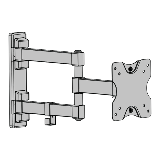
Resumen de contenidos para Steren STV-024
- Página 1 STV-024-V1.0-instr.pdf 17/08/16 10:02 a.m. STV-024 Soporte ultra delgado para pantalla LCD / LED de 14 - 24” V1.0 Manual de Usuario 0816A...
- Página 2 STV-024-V1.0-instr.pdf 17/08/16 10:02 a.m. Antes de utilizar su nuevo producto, lea el siguiente instructivo • Este aparato NO está destinado para ser utilizado por personas con capacidades diferen- tes, a menos que cuenten con la preparación y supervisión adecuadas. • Este producto NO es un juguete; manténgalo fuera del alcance de los niños.
-
Página 3: Tabla De Contenido
STV-024-V1.0-instr.pdf 17/08/16 10:02 a.m. B (x1) Soporte Placa principal C (x2) E (x1) F (x1 ) G (x2) Tuercas Llave Llave Tornillos Pasacables hexagonal mariposa Allen Tornillos Tornillos Rondanas W-A (x3) W-B (x3) W-C (x3) Tornillos Taquetes Rondanas Contenido... -
Página 4: Herramientas Necesarias Para La Instalación
Herramientas necesarias para la instalación (No incluidas) Nivel de gota Steren no se hace responsable por daños materiales ni personales causados por mal uso o mala instalación. Es responsabilidad del usuario asegurarse de la correcta instalación y uso del producto, así... -
Página 5: Sobre Concreto
STV-024-V1.0-instr.pdf 17/08/16 10:02 a.m. a) Sobre concreto 60mm (2.4") ø 10mm (ø 3/8") √ Instalación... -
Página 6: Sobre Madera
STV-024-V1.0-instr.pdf 17/08/16 10:02 a.m. b) Sobre madera 55mm (2.2") ø 4.5mm (ø 3/16") Recuerde que la madera debe estar en óptimas condiciones. No coloque el soporte sobre madera comprimida o húmeda. √ Instalación... -
Página 7: D ( X1)
STV-024-V1.0-instr.pdf 17/08/16 10:02 a.m. Coloque firmemente el protector de la base del soporte y el pasacables como se muestra en la imagen: Instalación... -
Página 8: Instalación De La Pantalla
STV-024-V1.0-instr.pdf 17/08/16 10:02 a.m. Instalación de la pantalla 1. Coloque los tornillos (G) en la placa principal, como se muestra en la imagen. 2. Atornille la placa en la parte posterior de la pantalla y fijelos. Los tornillos suministrados son de medidas estándar. Le recomendamos consultar el manual de instrucciones de su pantalla para obtener información... - Página 9 STV-024-V1.0-instr.pdf 17/08/16 10:02 a.m. 3. Coloque la pantalla (con la placa principal montada) en el soporte, como se muestra en la imagen. 4. Utilice las tuercas mariposa para asegurar la placa. Instalación...
-
Página 10: F (X1 )
STV-024-V1.0-instr.pdf 17/08/16 10:02 a.m. 5. Con ayuda de la llave Allen y la llave hexagonal afloje las piezas de las areas señaladas. coloque los cables enel pasacables. 6. Ajuste el ángulo de visión a la posición deseada, y apriete nuevamente las tuercas y tornillos. - Página 11 STV-024-V1.0-instr.pdf 17/08/16 10:02 a.m.
- Página 12 STV-024-V1.0-instr.pdf 17/08/16 10:02 a.m. STV-024 14 - 24” ultra slim LCD / LED TV stand V1.0 Instruction Manual 0816A...
- Página 13 STV-024-V1.0-instr.pdf 17/08/16 10:02 a.m. • Before using your product, please read the following instructions • This device cannot be used by people with different habilities, at less they have preparation and supervision. • This product is NOT a toy; keep it away from...
-
Página 14: M-C
STV-024-V1.0-instr.pdf 17/08/16 10:02 a.m. B (x1) A (x1) Support Plate C (x2) D (x1) E (x1) F (x1) G (x2) Threaded Hasp Allen Hexagon Screws Screws Screws Washers W-A (x3) W-B (x3) W-C (x3) Washers Dowels Washers Content... -
Página 15: Tools You May Need
Not included Level drop Steren it is not responsible by materials or personal damage caused by improper use or improper installation. Is responsibility of the user to be sure of the correct installation and the use of the product, as well as of their constant revision. - Página 16 STV-024-V1.0-instr.pdf 17/08/16 10:02 a.m. a) Installation in concrete 60mm (2.4") ø 10mm (ø 3/8") √ Installation...
- Página 17 STV-024-V1.0-instr.pdf 17/08/16 10:02 a.m. b) Installation in wood 55mm (2.2") ø 4.5mm (ø 3/16") Remember: the wood must be in optimal conditions. Don’t place the support over compressed or wet wood. √ Installation...
- Página 18 STV-024-V1.0-instr.pdf 17/08/16 10:02 a.m. 1. Place the protector firmly stand base and hasp shown on the image Installation...
- Página 19 STV-024-V1.0-instr.pdf 17/08/16 10:02 a.m. Screen installation 2. Place the fastening bars into the rear of the screen and choose 4 screws and washers to x them. The supplied screws are standard size. Please refers to the instruction manual of your screen to obtain more info about of the screws to mount in the support.
- Página 20 STV-024-V1.0-instr.pdf 17/08/16 10:02 a.m. 3. Insert the screen with the main board mounted on the support as shown in the picture 4. Use wing nuts to secure the plate Installation...
- Página 21 STV-024-V1.0-instr.pdf 17/08/16 10:02 a.m. 5. Loosen the areas designated to put the support in the desired position, place the wires into the hasp. 6. Adjust the viewing angle to the desired position and retighten the nuts and bolts. 1 8 0 °...
- Página 22 STV-024-V1.0-instr.pdf 17/08/16 10:02 a.m.


