Publicidad
Enlaces rápidos
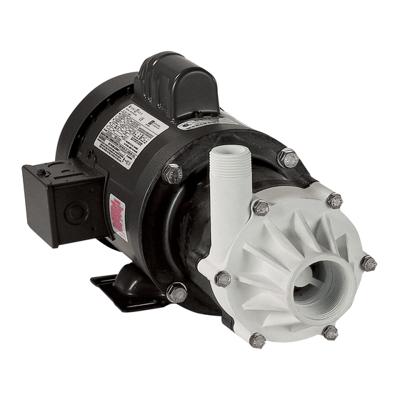
Note: Motor configuration may vary from model to model.
Remarque : La configuration du moteur peut varier selon le modèle.
Nota: La configuración del motor puede variar de modelo a modelo.
rePlacement Parts list
Part
descriPtion
no.
1
187005
Volute
1
187019
Volute
2
187056
Shaft, impeller
3
187085
Thrust washer
4
187172
Impeller assembly (3.75" diameter)
4
187208
Impeller assembly (3.75" diameter)
5
187023
Backplate
6
187073
Housing, magnet
7
187121
Drive magnet/holder assembly
8
924016
O-ring seal (Fluoroelastomer (FKM))
9
903712
Bolt, 1/4" (316 SS)
10
903713
Bolt, 3/8" (316 SS)
11
921050
Washer, 1/4" (316 SS)
12
921051
Washer, 3/8" (316 SS)
13
979450
Motor
13
979452
Motor
13
979451
Motor, 3-phase
14
187080
Bushing, impeller, carbon
For technical assistance please contact . . . . . . . . . . . . . . . . . . . . . . . . . . . 800 .701 .7894
Pour l'aide technique entrez s'il vous plaît en contact . . . . . . . . . . . . . . . 800 .701 .7894
Para la ayuda técnica por favor póngase en contacto . . . . . . . . . . . . . . . . 800 .701 .7894
www .LittleGiantPump .com
CustomerService@lgpc .com .com
PUmP model & catalog no.
1
1
1
1
1
1
1
1
2
2
2
2
1
1
1
1
1
1
1
1
1
1
1
1
1
1
1
1
1
1
1
1
6
6
6
6
4
4
4
4
6
6
6
6
4
4
4
4
1
1
1
1
1
1
1
1
Form 993317 - 06/2012 Rev. 001
Little Giant® is a registered trademark of Franklin Electric Co., Inc.
Franklin electric
Oklahoma City, OK 73127
www.LittleGiantPump.com
CustomerService@lgpc.com
PUmP constrUction
The patented Little Giant magnetic drive pump design consists of a cylindrical drive magnet attached to the motor
shaft, which rotates around a chemical resistant plastic separator housing. Inside this housing is a magnet completely
encapsulated in stainless steel, and fixed to the impeller. The impeller assembly is free to rotate on a spindle that is
supported at both ends. The spindle is held captive and does not turn. Front and rear thrust washers are utilized as
wear bearings. The washers are held captive and do not revolve. This prevents wear on the shaft. With the magnetic
coupling the motor drives the impeller. This coupling eliminates the conventional shaft seal and its possibility of leakage.
These models utilize a carbon bushing between the impeller and spindle. The use of this carbon bushing will allow these
pumps (SC & HC) to run dry (without fluid) for up to 8 hours with no apparent detrimental harm to pump. All wetted parts
can be serviced by removing (6) bolts which hold the volute to the housing. The pump head components can easily be
replaced in the field if necessary.
The plastic magnet housing on the SS series pumps is glass filled PPS. The spindle shaft, which is stationary, and
the captive thrust washers (front and rear) are alumina ceramic. If one side of thrust washer has a small black dot or
indentation mark, the reverse side is polished. The polished side interfaces with the spinning impeller. The O-ring seal
is Fluoroelastomer (FKM). Utilizing a pure carbon bushing in the impeller enables the pump to run dry for periods up to
eight hours.
Your Little Giant pump is delivered to you pretested from the factory. In order to prevent damage to the ceramic impeller
shaft during shipping, the impeller (item 4) has not been assembled within the pump head. The pump may be installed
in any position. It may be mounted vertically with the pump head down. Proper plumbing connections should be made.
See specification table to determine what size intake and discharge your pump has. Use a thread sealer on all pipe
connections and hand tighten only. Note: a roll of PTFE pipe seal tape is supplied. Do not use a wrench to tighten the
connections. Excessive force may damage the plastic part. Make sure the bolts are tight before operating the pump.
The motor nameplate lists all data. Make sure the pump is wired according to diagram under wiring compartment cover.
These pumps are not submersible. Operate the pumps only in the in-line mode. Do not put the units in liquid. Pump should
be installed in a dry area and protected from splash. These pumps are not self-priming. IMPORTANT: These pumps must
be installed so that the pump head (volute) is flooded before starting. That
is, the inlet of the pump must be below the level of the surface of the liquid
being pumped. (See Figure 1.)
Do not restrict the intake side of the pump. Connections on the intake side
should not be of smaller inside diameter pipe or tubing or hose than the
intake inside diameter of the intake thread designation. If reduced flow
is required restrict the discharge side. Installing a valve or other type of
restriction device on the discharge side is the proper method for reducing
flow from the pump. When using a valve the pump can be throttled to provide
various flow rates and pressures without harming the motor or the pump parts.
The pump should not be installed in a manner that will subject it to splashing or spraying.
caUtion: For connection to discharge and intake on all hc series pumps, use PtFe tape and hand tighten only.
Wrench will crack volute.
service instrUctions
Make certain that the unit is disconnected from the power source before servicing. Servicing should be performed only by
a service center or qualified electrician.
1.
The motor contains ball bearings which do not require lubrication.
2.
All wetted parts can be serviced by removing the 6 bolts (item 9) that hold the volute to the housing. The pump head
components can easily be replaced in the field if necessary.
3.
Lightly clean any corrosion or debris which may clog the impeller.
4.
If pump is tripping circuit breakers, GFCI, or not operating properly after cleaning, return it to a Little Giant authorized
service center. DO NOT attempt repairs yourself.
te-7-md-sc
te-7-md-hc
materials
installation
Figure 1
Publicidad

Manuales relacionados para Little Giant TE-7-MD-SC


Resumen de contenidos para Little Giant TE-7-MD-SC
- Página 1 187172 Impeller assembly (3.75” diameter) Your Little Giant pump is delivered to you pretested from the factory. In order to prevent damage to the ceramic impeller 187208 Impeller assembly (3.75” diameter) shaft during shipping, the impeller (item 4) has not been assembled within the pump head. The pump may be installed...
- Página 2 Votre pompe Little Giant vous est livrée complètement préassemblée et prétestée par l’usine. Elle est prête à être utilisée. La instalacion pompe peut être installée dans n’importe quelle position, dont verticalement avec la tête en bas. S’assurer de relier les bons tuyaux à...