Tabla de contenido
Publicidad
Idiomas disponibles
Idiomas disponibles
Enlaces rápidos
H8060B-1
200W Vermogenversterker ...................................................
Amplificateur de puissance 200W .......................................
200W-Leistungsverstärker ...................................................
Amplificador de potencia 200W ...........................................
K8060
3
8
13
18
Publicidad
Tabla de contenido

Manuales relacionados para Velleman K8060


Resumen de contenidos para Velleman K8060
- Página 1 K8060 200W Vermogenversterker ........... Amplificateur de puissance 200W ........200W-Leistungsverstärker ........... Amplificador de potencia 200W ........... H8060B-1...
- Página 2 VELLEMAN NV Legen Heirweg 33 9890 Gavere Belgium Europe www.velleman.be www.velleman-kit.com...
-
Página 3: Specificaties
200W VERMOGENVERSTERKER SPECIFICATIES : Uitstekende verhouding prijs/kwaliteit Ontwerp met Epitaxial Darlington transistors DC voedingscircuit met LED-aanduiding Ideaal voor actief luidsprekersysteem of subwoofer, gitaarversterker, home theatre-systeem, instrumentenversterker… Wordt geleverd met transistorisolatoren, afstandsbussen en bouten Bescherming tegen overbelasting en kortsluiting TECHNISCHE GEGEVENS : ... -
Página 4: Alvorens Te Beginnen
ALVORENS TE BEGINNEN Zie ook de algemene handleiding voor soldeertips en andere algemene informatie Benodigdheden om de kit te bouwen: Kleine soldeerbout van max 40W. Dun 1mm soldeersel, zonder soldeervet. Een kleine kniptang. 1. Monteer de onderdelen correct op de print zoals in de illustraties. 2. - Página 5 Monteer de keramische condensatoren. Monteer de trimpotentiometer. Monteer de transistors. Monteer de LED. Let op de polariteit! 10. Monteer de printpennen. 11. Monteer de elektrolytische condensatoren C9 ... C11. Let op de polariteit! 12. Monteer de PCB connectoren voor LS+, AC, AC-0, LS-, AC0 en AC. 13.
-
Página 6: Test En Afstelling
Sluit de transformator aan op de AC-aansluitingen van de PCB. De Velleman kleurencode voor de transformator is aangeduid op de PCB. Let op: bij andere merken kan de kleurencode volledig anders zijn, respecteer de spanning aanduiding! Y: geel, R: rood, B: blauw, G: grijs. - Página 7 TIP: een veiligheidstest: plaats een lamp van 60W in serie met de AC-voeding en de transformator. Wanneer u de voeding aanlegt en de lamp licht continu op, is er een probleem. Koppel de transformator los en controleer de PCB en de bedrading. Als u de voeding aanlegt en de lamp brandt niet, is alles OK en kunt u de lamp vervangen door een zekering.
-
Página 8: Amplificateur De Puissance 200W
AMPLIFICATEUR DE PUISSANCE 200W SPECIFICATIONS : Excellent rapport qualité/prix Conception utilisant des transistors Darlington Epitaxial. Alimentation CC sur le circuit avec indication LED Idéal pour des systèmes d'enceintes ou des subwoofers actifs, des amplificateurs pour guitare, des systèmes home cinéma, amplificateurs pour instruments…... - Página 9 AVANT DE COMMENCER Lisez également les astuces pour le soudage et d'autres infos générales dans la notice. Matériel nécessaire pour le montage du kit: Petit fer à souder de max. 40W. Fine soudure de 1mm, sans pâte à souder. ...
-
Página 10: Assemblage Final
Montez les condensateurs céramique. Montez la résistance trimmer. Montez les transistors. Montez la LED. Attention à la polarité! 10. Montez les broches. 11. Montez les condensateurs électrolytiques C9… C11. Attention à la polarité! 12. Montez les connecteurs PCB pour LS+, AC, AC-0, LS-, AC0 et AC. ! 13. - Página 11 Connectez le transformateur aux connecteurs CA du PCB. Le code des couleurs du transformateur Velleman est indiqué sur le PCB. Attention: d'autres marques peuvent utiliser un différent code de couleurs, Respectez les indications de voltage! Y: jaune, R: rouge, B: bleu, G: gris.
- Página 12 CONSEIL: pour exécuter un premier test en toute sécurité, mettez une ampoule 60W en série avec l'alimentation CA et le transformateur. Si l'ampoule s'allume continu , déconnectez le transformateur et contrôlez le PCB et son câblage. Remettez l'alimentation ; si l'ampoule ne s'allume pas, tout est en ordre. Remplacez l'ampoule par un fusible Si le transformateur TR8040 est utilisé, il faut sélectionner le voltage CA primaire : ...
-
Página 13: Technische Eigenschaften
200W-LEISTUNGSVERSTARKER TECHNISCHE EIGENSCHAFTEN Ausgezeichnetes Preis-/Leistungsverhältnis Entwurf mit epitaktischen Darlington-Transistoren Eingebaute DC-Spannungsversorgung mit LED-Anzeige Ideal für aktive Lautsprechersysteme oder Subwoofer, Gitarrenverstärker, Heimkino-Systeme, Instrumentenverstärker…. Geliefert mit Isolatoren, Distanzscheiben und Bolzen Überlastungs- und Kurzschlussschutz TECHNISCHE DATEN 200W Musikleistung @ 4 Ohm Last ... -
Página 14: Bevor Sie Anfangen
BEVOR SIE ANFANGEN Siehe auch die allgemeine Anleitung für Löthinweise und andere allgemeine Informationen Zum Bau notwendiges Material: Kleiner Lötkolben von höchstens 40W. Dünnes Lötmetall von 1mm, ohne Lötfett. Eine kleine Kneifzange. 1. Montieren Sie die Bauteile in der richtigen Richtung auf der Leiterplatte, siehe Abbildung. 2. - Página 15 Montieren Sie die keramischenkondensantoren. Montieren Sie das Trimmpotentiometer. Montieren Sie die Transistoren. Montieren Sie die LED. Achten Sie auf die Polarität! 10. Montieren Sie die Leiterplattenstifte. 11. Montieren Sie die Elektrolytkondensatoren C9… C11. Achten Sie auf die Polarität! 12. Montieren Sie die Leiterplattenstifte für LS+, AC, AC-0, LS-, AC0 und AC. 13.
- Página 16 Verbinden Sie den Transformator mit den AC-Stromanschlüssen der Leiterplatte. Die Farbübersicht der Velleman Transformatoren steht auf der Leiterplatte. Vorsicht: andere Marken könnten eine andere Farbübersicht haben, Beachten Sie die angezeigte Spannung! Y: gelb, R: rot, B: blau, G: grau.
- Página 17 HINWEIS: für einen sicheren ersten Test verwenden Sie eine 60W-Birne, die mit der AC-Stromversorgung und dem Transformator in Reihe geschaltet ist. Wenn die Birne noch immer brennt, trennen Sie den Transformator und überprüfen Sie alle Kabel und Ihre Aufstellung. Wenn alle Tests OK sind, ersetzen Sie die Birne durch eine Sicherung. Wenn der TR8040 Transformator verwendet wird, gibt es eine Primärspannungsauswahl: ...
-
Página 18: Amplificador De Potencia 200W
AMPLIFICADOR DE POTENCIA 200W ESPECIFICACIONES : Excelente relación precio/calidad Diseño que utiliza transistores Darlington Epitaxial Alimentación CC en el circuito con indicación LED Ideal para sistemas de altavoces o subwoofer activos, amplificadores para guitarra, sistemas ‘home cinema’, amplificadores para instrumentos…... -
Página 19: Antes De Empezar
ANTES DE EMPEZAR Lea también el manual del usuario para consejos de soldadura y otras informaciones generales. Material necesario para el montaje del kit : Pequeño soldador de 40W máx. Soldadura de 1mm, sin pasta de soldadura. Pequeños alicates de corte. -
Página 20: Importante
Monte los condensadores cerámicos. Monte el potenciómetro ajustable. Monte los transistores. Monte el LED. ¡Controle la polaridad! 10. Monte los polos. 11. Monte los condensadores electrolíticos C9 ... C11. ¡Controle la polaridad! 12. Monte los conectores CI para LS+, AC, AC-0, LS-, AC0 y AC. 13. -
Página 21: Montar El Transistor T6 En El Disipador De Calor
Conecte el transformador a los conectores de potencia CA del CI. El código de colores del transformador Velleman está en el CI. ¡Cuidado: otras marcas pueden utilizar otro código de colores, respete las indicaciones en relación con la tensión! Y: amarillo, R: rojo, B: azul, G: gris. - Página 22 CONSEJO: para realizar una primera prueba de forma completamente segura, conecte una bombilla de 60W en serie a la alimentación CA y el transformador. Si la bombilla se ilumina, desconecte el transformador y controle el CI y el cableado. Vuelva a activar la alimentación ;...
- Página 24 VELLEMAN NV Legen Heirweg 33, B-9890 GAVERE Belgium (Europe) Modifications and typographical errors reserved © Velleman nv. H8060B’1 - 2014 (rev.4) 5 4 1 0 3 2 9 3 4 0 6 7 4...
- Página 25 200W DISCRETE POWER AMPLIFIER K8060 H8060IP-1...
- Página 26 Features & Specifications Specifications: Excellent value for money Full discrete design using Epitaxial Darlington transistors DC supply circuit on board with LED indication Ideal for active speaker system or sub woofer, guitar amp, home theatre systems, instruments amp…. ...
- Página 27 Assembly hints 1. Assembly (Skipping this can lead to troubles ! ) Ok, so we have your attention. These hints will help you to make this project successful. Read them carefully. 1.1 Make sure you have the right tools: A good quality soldering iron (25-40W) with a small tip.
- Página 28 Assembly hints 1.3 Soldering Hints : 1- Mount the component against the PCB surface and carefully solder the leads 2- Make sure the solder joints are cone-shaped and shiny 3- Trim excess leads as close as possible to the solder joint REMOVE THEM FROM THE TAPE ONE AT A TIME ! AXIAL COMPONENTS ARE TAPED IN THE CORRECT MOUNTING SEQUENCE !
- Página 29 Construction R3 : 3K3 1. Diodes. Watch the polarity ! 4. Transistor connections (3 - 3 - 2 - B) R4 : 330 (3 - 3 - 1 - B) R5 : 220 (2 - 2 - 1 - B) ...
- Página 30 Construction & connection 7. Trim potentiometer 5. Power diodes. 10. PCB tabs. Watch the polarity ! RV1 : 1K IN D3 : 1N5404 GND D4 : 1N5404 D5 : 1N5404 D... D6 : 1N5404 CATHODE 11.
-
Página 31: Important
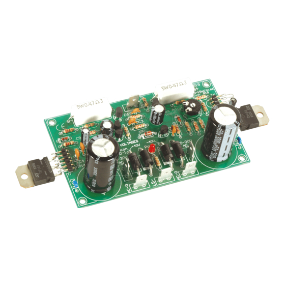
Construction 13. 5W resistors R... R19 : 0,47 R20 : 0,47 IMPORTANT 14. Electrolytic Capacitors. Watch the polarity ! Check the complete assembly carefully before mounting the heat sink. C12 : 3300µF C13 : 3300µF ... -
Página 32: Final Assembly
Final Assembly 15. Final assembly A custom pre-drilled heat sink is available from your distributor (order code HSVM100). Any other heat sink must be able to dissipate at least 30W (1.25°C/W) (see fig.1.0). Use the template as a drill guide Fig. - Página 33 Final assembly Mount 4 bolts + 8 nuts (PCB support). (fig.2.0) Slide the PCB over the 4 bolts, and fix using 4 nuts (Fig 3.0). 2 x M3 nut Fig. 3.0 M3 15mm bolt Fig. 2.0...
- Página 34 Transistor T6 16. Mounting the transistor T6 on the heat sink: Apply a drop of heat conductive compound in the heat sink hole (fig. 4.0). Fig. 4.0...
- Página 35 Transistor T6 Insert the transistor (BC547) in the hole (Fig. 5.0). Pay attention to the position of the transistor (fig 6.0)! BC547 Fig. 5.0 Fig. 6.0 Carefully bend the leads and solder them to the connector T6, see figure 7.0.
- Página 36 Power transistors 17. Mounting of the power transistors T7 (TIP147) and T8 (TIP142). M3 nut Lock washer Apply a drop of heat conductive compound on the heat sink (see fig 8.0.) washer plastic isolation Mount the isolation mica onto the heat sink, check the position of the hole. washer Apply a drop of heat conductive compound on the mica.
- Página 37 Power transistors Solder the connections of the power transistors with the pin headers, see fig. 10. Fig. 10...
- Página 38 Use a 2 x 25 to 30Vac / 100 - 120VA transformer. Connect the transformer to the AC power connections of the PCB. The Velleman transformer colour scheme is specified on the pcb. Careful : Other brands may feature a different scheme ! SOLDER Y: yellow, R: red, B: blue, G: grey.
- Página 39 Test & adjustments...
- Página 40 Test & adjustments Turn the RV1 bias adjust trimmer fully counter clockwise (turn left) before applying power for the first time. ADVICE: For safe first-time testing insert a 60W light bulb in series with the AC power and the transform- er.
- Página 41 Test & adjustments Final connection: The input (GND and in) can be connected directly to an audio source (pre-amp or mixing panel) or a vol- ume control (potentiometer) can be used (see diagram). Connect the speaker (4 ohm or higher) to the connections LS+ and GND. ...
- Página 42 Diagram 19. Diagram +40V +40V 1N5404 +40V 100nF 4700µ/50V AC-0 1N5404 680p AC-0 TIP142 LED3RL 1N5404 100nF 4700µ/50V +40V 1N4148 1N5404 -40V Bias current (cold) BC547 10-15mV over R19 220R 0.47 / 5W ZB9V1 100µ/50V 500R BC547 Bias adj. 0.47 / 5W 47nF BC640 BC640...
- Página 44 VELLEMAN NV Legen Heirweg 33, B-9890 GAVERE Belgium (Europe) Modifications and typographical errors reserved © Velleman nv. H8060IP - 2014 - ED1 (rev.3) 5 4 1 0 3 2 9 3 3 5 0 7 6...