Tabla de contenido
Publicidad
Idiomas disponibles
Idiomas disponibles
Enlaces rápidos
ENGLISH INSTRUCTIONS
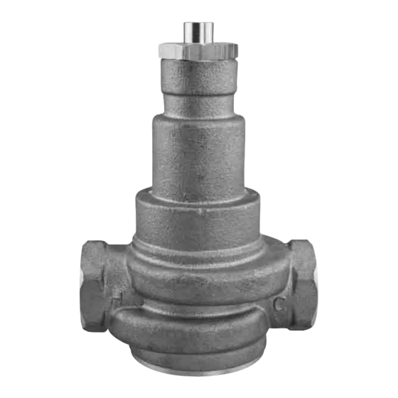
Series N170-M3 and LFN170-M3
Hot Water Master Tempering Valves
!
W ARNI NG
You are required to thoroughly read all installation instructions and
product safety information before beginning the installation of this prod-
uct. FAILURE TO COMPLY WITH PROPER INSTALLATION AND
MAINTENANCE INSTRUCTIONS COULD RESULT IN PRODUCT
FAILURE WHICH CAN CAUSE PROPERTY DAMAGE, PERSONAL
INJURY AND/OR DEATH. Watts is not responsible for damages result-
ing from improper installation and/or maintenance.
Local building or plumbing codes may require modifications to the
information provided. You are required to consult the local building and
plumbing codes prior to installation. If this information is not consistent
with local building or plumbing codes, the local codes should be fol-
lowed.
Installation Instructions
Installation should be in accordance with acceptable plumbing prac-
tices. Flush all pipes thoroughly before installation. Installation and field
adjustment are responsibility of the installer and shall be carried out per
following installation instructions.
1. Valves are to be installed as close to building inlet supply as possible
to prevent/minimize pressure fluctuations.
2. Valve body can be installed in multiple positions, see below. Make
sure that the union nuts and tailpieces are tightened securely if you
are using checkstops.
3. Connect inlets and outlet and check for leaks.
!
4.
CAUTION: When N170-M3 or LFN170-M3 supplies tempered
water to self-closing and/or solenoid valves, provide a shock absorb-
er on the discharge line.
5. Before use, check discharge temperature. Reset if necessary
Temperature Adjustment
1. Turn off recirculation pump (if one is in the system).
2. Open enough fixtures to meet the minimum flow requirement of the
valve.
3. Loosen the lock nut. Turn temperature adjustment screw clockwise
to decrease or counterclockwise to increase outlet temperature.
NOTE: Please allow valve temperature to stabilize in before making
your next adjustment. Watts recommends that a temperature gauge is
installed on the tempered line and be checked at least monthly under
normal flow conditions. The gauge must be installed at least 6 ft. away
from the tempering valve.
4. When desired temperature is set, tighten the lock nut. Turn recircu-
lation pump back on. Close open fixtures.
LFN170-M3
FRONT OUTLET
!
WA R N I N G
Watts Hot Water Master Tempering Valves cannot be used for
tempering water temperature at fixtures. Severe bodily injury (i.e.,
scalding or chilling) and/or death may result depending upon system
water pressure changes and/or supply water temperature changes.
ASSE standard 1016, 1069 or 1070 listed devices such as Watts
Series MMV, LFMMV, USG, LFUSG, L111 or LFL111 valves should be
used at fixtures to prevent possible injury.
The Watts Hot Water Tempering Valves are designed to be installed at
or near the boiler or water heater. They are not designed to compensate
for system pressure fluctuations and should not be used where ASSE
standard 1016, 1069 or 1070 devices are required. These Watts valves
should never be used to provide "anti-scald" or "anti-chill" service.
!
WA R N I N G
Need for Periodic Inspection: Periodic inspection by a licensed
contractor is recommended. Corrosive water conditions, tempera-
tures over 210°F, unauthorized adjustments or repair could render
the valve ineffective for service intended. Regular checking and
cleaning of the valves internal components and checkstops helps
to assure maximum life and proper product function. Frequency of
cleaning depends upon local water conditions.
IS-N170-M3
N170-M3 CSUT
BACK OUTLET
TOP OUTLET
Publicidad
Tabla de contenido

Manuales relacionados para Watts N170-M3 Serie


Resumen de contenidos para Watts N170-M3 Serie
- Página 1 3. Loosen the lock nut. Turn temperature adjustment screw clockwise The Watts Hot Water Tempering Valves are designed to be installed at to decrease or counterclockwise to increase outlet temperature. or near the boiler or water heater. They are not designed to compensate...
-
Página 2: Basic Installation
NOTE: Heat trap is recommended. Minimum Flow Requirements to † Valves listed to ASSE Standard 1016, 1069 Maintain Set Temperature or 1070, such as the Watts L111, LFL111, for N170-M3 or LFN170-M3 Series USG, LFUSG, MMV, or LFMMV should be Valve Size used at point of delivery. - Página 3 A Two Temperature Recirculating Hot Water Supply System Recirculation System 1 To Fixture Series Cold Water Supply To MMV, USG-B, L111 or LFL111 then to fixtures Thermometer Aquastat WATTS CSA/ASME Temperature & Circulator Pressure Relief Valve WATTS WATTS Check Ball Valves...
- Página 4 Circulator Limited Warranty: Watts Regulator Co. (the “Company”) warrants each product to be free from defects in material and workmanship under normal usage for a period of one year from the date of original shipment. In the event of such defects within the warranty period, the Company will, at its option, replace or recondition the product without charge.
- Página 5 LFUSG, L111 o LFL111, para evitar posibles lesiones. 2. Abra suficientes accesorios como para que pase el mínimo flujo Las válvulas de templado de agua caliente de Watts están diseñadas requerido para la válvula. para ser instaladas cerca de la caldera o del calentador de agua. No están diseñadas para compensar las fluctuaciones de presión del...
-
Página 6: Instalación Básica
ASSE 1016, 1069 para las series N170-M3 o LFN170-M3 ó 1070, como las Watts L111, LFL111, USG, Tamaño de la válvula LFUSG, MMV, o LFMMV. 20 a 50 mm (¾ a 2 pulg.) 11 a 26,5 lpm (3 a 7 gpm) Especificaciones •... -
Página 7: Sistema De Recirculación
Sistema de recirculación 1 Al accesorio Serie Suministro de agua fría A MMV, USG-B, L111 o LFL111 , luego a los Termómetro accesorios Termostato para el agua WATTS CSA/ASME Válvula de temperatura Circulador Válvulas y liberación de presión Válvula retención esférica WATTS WATTS... - Página 8 USG, LFUSG, MMV o LFMMV. Limitaciones: Watts Regulator Co. (la “Compañía”) garantiza cada producto contra defectos en el material y mano de obra bajo condiciones normales de uso por un periodo de un año a partir de la fecha del envío original.
-
Página 9: Réglage De La Température
2. Ouvrir suffisamment de robinets pour satisfaire au débit minimum de Les soupapes de mélange de l’eau chaude Watts sont conçues pour être la soupape. montées à proximité ou au niveau de la chaudière ou du chauffe-eau. -
Página 10: Installation De Base
REMARQUE : Piège à chaleur recommandé. Débits minimum des soupapes † Les soupapes homologuées ASSE, normes de Série N170-M3 ou LFN170-M3 1016, 1069 ou 1070, comme les Watts L111, pour maintenir la température réglée LFL111, USG, LFUSG, MMV ou LFMMV, Diam. de la soupape doivent être utilisées sur le lieu de livraison. -
Página 11: Circuit De Recirculation
Circuit de recirculation 1 Vers robinet Série Alimentation d’eau froide Vers MMV, USG-B, L111 ou LFL111, puis vers Thermomètre robinets Aquastat CSA/ASME de WATTS Robinet Pompe de Soupape de sûreté à tour- recirculation Clapets Température et Pression nant de non- sphéri-... - Página 12 Garantie limitée : Watts Regulator Co. (la « Société ») garantit chaque produit contre tout défaut de matériau et de fabrication lors d’une utilisation normale, et ce pour une période de un (1) an à partir de la date de l’expédition d’origine. Si une telle défaillance devait se produire au cours de la période sous garantie, la Société aura à sa discrétion l’alternative suivante : le remplacement ou bien la remise en état du produit, sans frais pour le demandeur.