Tabla de contenido
Publicidad
Idiomas disponibles
Idiomas disponibles
Enlaces rápidos
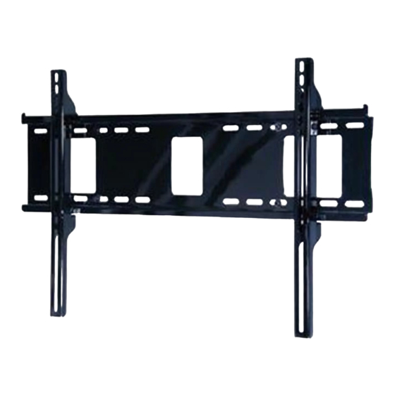
Model: PRTLU
Installation Guide
Paramount™ Universal Tilt Wall Mount
for 37" - 60" Flat Panel Screens
U L
C
US
Max UL Load Capacity: 200 lb (90 kg)
©
WARNING
This product was designed to be installed on wood stud walls and solid concrete (2000 psi
density minimum) or cinder block walls. Before installing make sure the supporting surface will
support the combined load of the equipment and hardware. Screws must be tightly secured. Do
not overtighten screws or damage can occur or product may fail. Never exceed the Maximum UL
Load Capacity. This product is intended for indoor use only. Use of this product outdoors could
lead to product failure or personal injury. For support please call customer care at 1-800-865-2112.
ISSUED: 11-03-09 SHEET #: 202-9395-1
Publicidad
Tabla de contenido

Manuales relacionados para PEERLESS PARAMOUNT PRTLU


Resumen de contenidos para PEERLESS PARAMOUNT PRTLU
- Página 1 Model: PRTLU Installation Guide Paramount™ Universal Tilt Wall Mount for 37" - 60" Flat Panel Screens Max UL Load Capacity: 200 lb (90 kg) © WARNING This product was designed to be installed on wood stud walls and solid concrete (2000 psi density minimum) or cinder block walls.
-
Página 2: Tools Needed For Assembly
Tools Needed for Assembly • stud finder ("edge to edge" stud finder is recommended) • phillips screwdriver • drill ( 1 ) • 5/32" (4 mm) bit for wood stud wall • 5/16" (8 mm) bit for concrete and cinder block • level • hammer (optional) ( 1 ) ( 1 ) ( 4 ) ( 4 ) M4 x 25 mm M5 x 12 mm ( 4 ) ( 4 ) -
Página 3: Installation To Double Wood Stud Wall
Installation to Double Wood Stud Wall Use wall plate (A) as a template, make sure it is level, and mark four mounting holes along the center lines of the wood studs. Drill four 5/32" (4 mm) dia. holes 2.5" (64 mm) deep. Level wall plate (A) and attach to wall with four wood screws (D) into stud center. Use of an edge to edge stud finder is highly recommended. Tighten screws firmly, but do not overtighten. WARNING WARNING Wood screws must center in stud. - Página 4 Installing to Solid Concrete or Cinder Block Level wall plate (A) and use as a template to mark four mounting holes. Drill four 5/16" (8 mm) dia. holes to a minimum depth of 2.5" (64 mm). Insert four anchors (E) into holes and secure wall plate (A) with four screws (D). Tighten screws firmly, but do not overtighten. SOLID CONCRETE CINDER BLOCK 4 of 32 ISSUED: 11-03-09 SHEET #: 202-9395-1...
- Página 5 WARNING • When installing Peerless wall mounts on cinder block, verify that you have a minimum of 1-3/8" (35 mm) of actual concrete thickness in the hole to be used for the concrete anchors. Do not drill into mortar joints! Be sure to mount in a solid part of the block, gener- ally 1" (25 mm) minimum from the side of the block. Cinder block must meet ASTM C-90 specifications. It is suggested that a standard electric drill on slow setting is used to drill the...
-
Página 6: Installing Adapter Brackets
Installing Adapter Brackets To prevent scratching the screen, set a cloth on a flat, level surface that will support the weight of the screen. Place screen face side down. Refer to screen manufacturers instruc- tions or customer service, for removing any knobs, base, cover, or screw(s) on the back of the screen to prepare mounting. These need to be removed to allow the adapter brackets to be attached. Select the small, medium, large or extra large screws from the baffled fastener pack then attach tilt brackets to screen following figure 2.1 or 2.2. - Página 7 ADAPTER BRACKET (B or C) If you have any questions, please call Peerless customer care at 1-800-865-2112. For Bump-out or Recessed Back Screen Refer to screen compatibility chart to determine the proper fastener to use. Visit www.peerlessmounts.com/2 for a full screen compatibility chart for this mount.
- Página 8 Mounting and Removing Flat Panel Screen Tension Adjustment of Ratchet Handle: Adjust tension in tilt brackets (B & C) by rotating ratchet handle. NOTE: If obstruction prevents ratchet handle from rotating, pull handle out while turning will allow handle to reposition without tightening. Release and turn handle to tighten or loosen. Mounting Screen: Ratchet handle must be in the up or down position or interference will occur while hooking tilt brackets to wall plate (A).
- Página 9 Screen Adjustment: Screen can be adjusted horizontally by loosening safety screws on tilt brackets (B & C) three full turns with a phillips screw driver. Adjust screen as shown in figure 3.2. Tighten safety screws on tilt brackets till screw tip securely contacts wall plate as shown in cross section. fig. 3.2 Adjusting the Tilt Angle of the Flat Panel Screen For preset tilt angles use Increlok™...
- Página 11 Capacidad Máxima (UL) de Carga. Este producto está diseñado para uso en interiores solamente. Utilizar este producto en exteriores podría causar fallas del producto o lesiones a individuos. Si necesita ayuda, por favor, llame a Servicio al Cliente de Peerless al 1-800-865-2112. PUBLICADO: 11-03-09 HOJA #: 202-9395-1...
-
Página 12: Herramientas Necesarias Para El Ensamblaje
Español Herramientas necesarias para el ensamblaje • localizador de montantes (se recomienda uno de "borde a borde") • destornillador phillips • taladro • broca de 5/32" (4 mm) para paredes ( 1 ) con montantes de madera • broca de 5/16" (8 mm) para concreto macizo o de bloques de hormigón de escorias • nivel • martillo (opcional) ( 1 ) ( 1 ) ( 4 ) -
Página 13: Instalación En Una Pared Con Montantes De Madera Dobles
Español Instalación en una pared con montantes de madera dobles Utilice la placa de pared (A) como plantilla, asegúrese de que esté nivelada y marque cautro agujeros de montaje a lo largo de las líneas que pasan por el centro de los montantes de madera. Taladre cautro agujeros de 5/32" (4 mm) de diámetro y 2.5" (64 mm) de profundidad. Nivele la placa de pared (A) y fíjela a la pared con cautro tornillos de madera (D) en el centro del montante. -
Página 14: Instalación En Una Pared De Concreto Macizo O De Bloques De Hormigón De Escorias
Español Instalación en una pared de concreto macizo o de bloques de hormigón de escorias Nivele la placa de pared (A) y úsela como plantilla para marcar cautro agujeros de montaje. Taladre cautro agujeros de 5/16" (8 mm) de diámetro a una profundidad mínima de 2 1/2" (64 mm). Inserte cautro anclajes (E) en los agujeros y fije la placa de pared (A) a la pared con cautro pernos largos (D). Apriete los tornillos con firmeza. No apriete los tornillos en exceso. - Página 15 Español ADVERTENCIA • Cuando vaya a instalar soportes de pared de Peerless en bloques de hormigón de esco- rias, asegúrese de que cuente con una capa de concreto de un grosor mínimo de 1-3/8" (35 mm) en el agujero, que pueda usar para los anclajes para concreto. ¡No taladre en juntas de argamasa! Asegúrese de hacer la instalación en la parte sólida del bloque, por lo general, a un mínimo de 1" (25 mm) del extremo del bloque. Los bloques de hormigón de escorias tienen que cumplir las especificaciones de la ASTM C-90. Se sugiere utilizar un...
- Página 16 Español Instalación de los soportes adaptadores Para no rayar la pantalla, coloque un trapo sobre una superficie plana y nivelada que sostenga el peso de la pantalla. Coloque la pantalla boca abajo. Si la pantalla tiene peril- las en la parte traera, quíteselas para poder fijar los soportes adaptadores. Coloque los soportes adaptadores (B o C) en la parte trasera de la pantalla, alinéelos con los agujeros y centralícelos en la parte trasera de la pantalla, como se muestra abajo.
- Página 17 ADAPTADOR (B o C) Si tiene alguna pregunta, por favor, llame a Servicio al Cliente de Peerless al 1-800-865-2112. Instalación de un televisor que tiene la parte posterior abultada o empotrada Consulte la Tabla de compatibilidad de las pantallas para determinar cuáles son los sujetadores adecuados para usarse.
-
Página 18: Montaje Y Desmontaje De La Pantalla Plana
Español Montaje y desmontaje de la pantalla plana Ajuste tensor de la palanca de trinquete: Ajuste la tensión de los soportes inclinables (B y C) rotando la palanca de trinquete. NOTA: Si una obstrucción le impide rotar la palanca de trinquete, pu- ede tirar de la palanca hacia fuera a la vez que le da vuelta para poder colocarla en otra posición sin apretar los soportes. - Página 19 Español Ajuste de la pantalla: La pantalla se puede ajustar horizontalmente aflojando los tornillos de seguridad de los soportes inclinables (B y C) tres vueltas completas. Ajuste la pan- talla, como se muestra en la figura 3.2. Apriete los tornillos de seguridad de los soportes inclinables hasta que la punta de los tornillos toque firmemente la placa de pared, como se muestra en la sección transversal. fig. 3.2 Ajustar el ángulo de inclinación de la pantalla Para colocar la pantalla en ángulos de inclinación predeterminados, utilice la función de IncreLok™; para ajustar la inclinación como guste, utilice la palanca de trinquete. INCRELOK™: La pantalla se puede ajustar a ángulos de inclinación predeterminados de -5°, 0°, 5°, 10°...
- Página 21 Modelle: PRTLU Montageanleitung Paramount™-Universal-Wandkipphalter für Flachbildschirme von 37- 60 Zoll Max. Tragfähigkeit (UL): 200 lb (90 kg) © ACHTUNG Dieses Produkt wurde für die Anbringung an Holzständerwänden und Massivbetonwänden (mit einer Druckfestigkeit von mindestens 2000 psi) oder porenbetonstein ausgelegt. Vergewissern Sie sich vor der Anbringung, dass die tragende Fläche das Gesamtgewicht der Geräte und der Befestigungsteile tragen kann.
- Página 22 Deutsch Für den Zusammenbau erforderliche Werkzeuge • Balkenfinder (Balkenfinder mit genauer Kantenanzeige empfohlen) • Kreuzschlitzschraubendreher • Bohrer • 5/32 Zoll (4 mm) Bit für ( 1 ) Holzständerwände • 5/16 Zoll (8 mm) Bit für Betonwände und Porenbetonstein • Wasserwaage • Hammer (optional) ( 1 ) ( 1 ) ( 4 ) ( 4 ) M4 x 25 mm M5 x 12 mm ( 4 )
-
Página 23: Anbringung An Holzständerwand
Deutsch Anbringung an Holzständerwand Verwenden Sie die Wandplatte (A) als Schablone, achten Sie darauf, dass sie waagerecht ausgerichtet ist, und markieren Sie vier Montagebohrungen entlang der Mittellinien der Holzstän- der. Bohren Sie vier Löcher mit einem Durchmesser von 4 mm (5/32 Zoll) und einer Tiefe von 64 mm (2.5 Zoll). Richten Sie die Wandplatte (A) waagerecht aus und bringen Sie sie mit vier langen Schrauben (D) an der Wand an in Mitte des Ständers. Am besten eignet sich ein Balkenfinder mit genauer Kantenanzeige. - Página 24 Deutsch Installation zu massivbeton oder porenbetonstein Richten Sie die Wandplatte (A) waagerecht aus und verwenden Sie sie als Schablone, um vier Montagebohrungen zu markieren. Bohren Sie vier Löcher mit einem Durchmesser von 8 mm (5/16 Zoll) und einer Mindesttiefe von 64 mm (2 1/2 Zoll ). Setzen Sie vier Dübel (E) in die Bohrungen ein und bringen Sie die Wandplatte (A) mit vier langen Schrauben (D) an der Wand an. Ziehen Sie die Schrauben fest an, ohne sie zu überdrehen.
- Página 25 Deutsch ACHTUNG • Bei der Anbringung von Peerless-Wandhaltern an Porenbetonstein muss sichergestellt werden, dass die tatsächliche Stärke des Betons, in den das Loch für die Betondübel ge- bohrt wird, mindestens 35 mm (1 3/8 Zoll) beträgt. Bohren Sie nicht in Mörtelfugen! Achten Sie darauf, dass die Anbringung an einem massiven Teil des Blocks erfolgt, im Allgemeinen mindestens 25 mm (1 Zoll) von der Blockseite entfernt. Die Porenbetonsteine müssen den Spezifikationen der ASTM-Norm C-90 entsprechen. Wir empfehlen, zum Bohren des Lochs...
-
Página 26: Anbringung Von Adapterhalterungen
Deutsch Anbringung von Adapterhalterungen Legen Sie ein Tuch auf eine flache, ebene Oberfläche, die das Gewicht des Bildschirms tragen kann, damit der Bildschirm nicht zerkratzt wird. Legen Sie den Bildschirm mit der Vorderseite nach unten ab. Lesen Sie die Anleitungen des Bildschirmherstellers bzw. des Kundendienstes bzgl. der Entfernung von Knöpfen, Sockel, Abdeckungen oder Schrauben auf der Rückseite des Bildschirms, um die Montage vorzubereiten. - Página 27 Halterungen waagerecht aus und ziehen Sie die Schrauben an. Abbildung 2.1 BILDSCHIRM ABSTANDHANDLER MEHRLOCHSCHEIBE SCHRAUBE ADAPTERHALTERUNG (B oder C) Wenden Sie sich mit Fragen an den Peerless-Kundendienst unter der Telefonnummer +1-800-865-2112 (innerhalb der USA). 27 von 32 AUSGEGEBEN:11-03-09 BLATT NR.: 202-9395-1...
- Página 28 Deutsch Anbringung und Abnahme des Flachbildschirms Spannungseinstellung mit Ratschengriff: Die Spannung in den Kipphalterungen (B und C) wird durch Drehen des Ratschengriffs eingestellt. HINWEIS: Falls das Drehen des Ratschengriffs durch etwas behindert wird, ziehen Sie den Griff beim Drehen heraus. Dadurch kann er ohne Festziehen neu positioniert werden.
- Página 29 Deutsch Bildschirmeinstellung: Der Bildschirm kann horizontal eingestellt werden, indem die Sicherheitsschrauben an den Kipphalterungen (B und C) mit einem Kreuzschlitzschraubendreher um drei volle Umdrehungen gelöst werden. Stellen Sie den Bildschirm wie in Abbildung 3.2 dargestellt ein. Ziehen Sie die Sicherheitsschrauben an den Kipphalterungen an, bis die Schraubenspitze wie im Schnittbild dargestellt sicher mit der Wandplatte Kontakt hat.
- Página 30 30 of 32 ISSUED: 11-03-09 SHEET #: 202-9395-1...
- Página 31 31 of 32 ISSUED: 11-03-09 SHEET #: 202-9395-1...
- Página 32 32 of 32 ISSUED: 11-03-09 SHEET #: 202-9395-1...