Tabla de contenido
Publicidad
Idiomas disponibles
Idiomas disponibles
Enlaces rápidos
allen + roth is a registered trademark
of LF, LLC. All Rights Reserved.
ATTACH YOUR RECEIPT HERE
Serial Number ___________ Purchase Date ___________
Questions, problems, missing parts? Before returning to your retailer, call our customer
e s
i v r
e c
d
e
p
a
t r
AR19063
welcoming
m
e
t n
t a
1
8 -
6
6
4 -
3
9
9 -
8
·
sophisticated
MODEL
0
, 0
8
. a
m
- .
8
. p
m
, .
E
S
1
·
inspiring
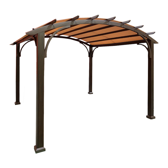
ITEM #1839858/ #2808040
PERGOLA
#TPPER9117/ #TPPER9117A
Español p. 15
, T
M
o
n
d
y a
-
r F
d i
a
. y
Publicidad
Tabla de contenido

Resumen de contenidos para allen+roth TPPER9117
- Página 1 + roth is a registered trademark of LF, LLC. All Rights Reserved. PERGOLA MODEL #TPPER9117/ #TPPER9117A Español p. 15 ATTACH YOUR RECEIPT HERE Serial Number ___________ Purchase Date ___________ Questions, problems, missing parts? Before returning to your retailer, call our customer...
-
Página 2: Package Contents
PACKAGE CONTENTS DESCRIPTION DESCRIPTION QUANTITY DESCRIPTION QUANTITY PART PART Ferrule Post Post Support Bar Arc Beam Support Bar Arc Beam Base Cover Beam Base Beam Sidewall Rod Top Beam Canopy Top Beam Sidewall Connector Canopy Holding Rod Arc Connector Canopy Holding Rod Ferrule... - Página 3 HARDWARE CONTENTS (shown actual size) Washer Plastic Washer Qty. 36 + 6 Extra Qty. 50 + 6 Extra × t l o Qty. 56+ 6 Extra M6 × 55 mm Bolt Qty. + 2 Extra M6 × 65 mm Bolt Qty.
-
Página 4: Safety Information
SAFETY INFORMATION Please read and understand this entire manual before attempting to assemble or install the product. Three people are need for assembly. WARNING: KEEP ALL FLAME AND HEAT AWAY FROM THIS GAZEBO FABRIC. l i b y t i continuous contact with any flame source. - Página 5 ASSEMBLY INSTRUCTIONS 1. Insert the posts (A1/A2) into the base cover (H), then attach the bases (I) to the posts (A1/A2) using bolts (AA) and washers (EE).Tighten with wrench (JJ). Place cap (HH) on the bolt heads. Hardware Used...
- Página 6 ASSEMBLY INSTRUCTIONS 2. Insert the connectors (E1) to the beams (C1), secure with bolts (AA) and plastic washers (FF), tighten with wrench (JJ). Place cap (HH) on the bolt heads. Hardware Used 3. Attach the ferrule (F1) to the beam assemblies (C1/E1).
- Página 7 ASSEMBLY INSTRUCTIONS 5. Attach the Sidewall Rod (J) to the Beam (C1/C2), secure with bolts (AA) and Plastic washers (FF), tighten with wrench (JJ). Place cap (HH) on the bolt heads. Hardware Used Insert arc connectors (E2) to the arc beams (B1), secure with bolts (AA) and plastic washers (FF), tighten with wrench (JJ).
- Página 8 ASSEMBLY INSTRUCTIONS 8. Attach the arc beams (B2) to the arc beam assemblies (B1/E2/F1) and secure with bolts (AA) and plastic washers (FF), tighten with wrench (JJ). Place cap (HH) on the bolt heads. Hardware Used 9. Connect the assembled arc beams (B1/B2) to posts (A1/A2) through the holes on the posts A1 A2 using bolts (BB) on a flat, non-abrasive surface.
- Página 9 ASSEMBLY INSTRUCTIONS 11. Attach the supports bar (G) to the posts (A1/A2) and the beams (C1/C2) using bolts (CC) and washers (EE), tighten with wrench (JJ). Repeat this B1 B2 step for attaching the supports bar (G1) to the posts (A1/A2) and the arc beams (B1/B2) using bolts (CC) and washers (EE), tighten with wrench (JJ).
- Página 10 ASSEMBLY INSTRUCTIONS 12. Have the Ferrule (F2) sleeved into the Top beam (D2), then sleeve the Top beam (D1) into the Top beam (D2). Secure with bolts (AA) and plastic washers (FF), tighten with wrench (JJ). Place cap (HH) on the bolt heads. Hardware Used...
- Página 11 ASSEMBLY INSTRUCTIONS 13. Attach the assembled top beams (D1/D2) to the arc beams (B1/B2) using bolts (DD) and plastic washers (FF), tighten with wrench (JJ). Place cap (HH) on the bolt heads. Note: Don’t attach the assembled top beams (D1/D2) to the holes on the outside of the arc beams (B1/B2).
- Página 12 ASSEMBLY INSTRUCTIONS 14. Connect Canopy Holding Rod (M1) and Canopy Holding Rod (M2), insert the assembed Canopy Holding Rod (M1/M2) into the Canopy (K), then secure the rod onto the Arc Beam (B1/B2) with the bolt (GG). Hardware Used 15. Put the Sidewall (L) onto the Sidewall Rod (J) by the Rings (II), then secure it onto the Posts (A1/A2).
-
Página 13: Care And Maintenance
CARE AND MAINTENANCE • For cleaning, use a mild detergent solution, rinse with water, and allow to air dry. Do not use acetone, abrasive, or other special detergents as they would be harmful to the product’s finish. • Due to the nature of steel, surface oxidation (rusting) will occur if this protective coating is scratched. This is a natural process. -
Página 14: Replacement Parts List
REPLACEMENT PARTS LIST For replacement parts, call our customer service department at 1-866-439-9800 8 a.m. - 8 p.m., EST, Monday - Friday. Washer Plastic Washer M6 × 15 mm Bolt M6 × 55 mm Bolt M6 × 65 mm Bolt M6 ×... - Página 15 + roth es una marca registrada de LF, LLC. Todos los derechos reservados. PÉRGOLA MODELO #TPPER9117/ #TPPER9117A ADJUNTE EL RECIBO AQUÍ Número de serie ___________ Fecha de compra ___________ ¿Preguntas, problemas, piezas faltantes? Antes de volver a la tienda, llame a nuestro Departamento de Servicio al Cliente al 1-866-439-9800, de lunes a viernes de 8 a.m.
-
Página 16: Contenido Del Paquete
CONTENIDO DEL PAQUETE PIEZA DESCRIPCIÓN DESCRIPTION CANTIDAD PIEZA DESCRIPCIÓN CANTIDAD Casquillo Poste Poste Barra de soporte Viga de arco Barra de soporte Viga de arco Cubierta de la base Viga Base Viga Varilla de la pared lateral Viga superior Toldo Viga superior Pared lateral Conector... -
Página 17: Aditamentos (Se Muestran En Tamaño Real)
ADITAMENTOS (se muestran en tamaño real) Arandela Cant. + 6 adicionales Arandela de plástico Perno M6 x 15 mm Cant. 50 + 6 adicionales Cant. 56 + 6 adicionales Perno M6 x 55 mm Cant. 16 + 2 adicionales Perno M6 x 65 mm Cant. -
Página 18: Información De Seguridad
INFORMACIÓN DE SEGURIDAD Lea y comprenda completamente este manual antes de intentar ensamblar o instalar el producto. Para realizar el ensamblaje se necesitan tres personas. ADVERTENCIA: MANTENGA LA TELA DE ESTE GAZEBO ALEJADA DE LAS LLAMAS Y EL CALOR. Este gazebo cumple con los requisitos de inflamabilidad de la norma CPAI-84. La tela puede quemarse si se encuentra en contacto continuo con cualquier fuente de llamas. -
Página 19: Instrucciones De Ensamblaje
INSTRUCCIONES DE ENSAMBLAJE 1. Inserte los postes (A1/A2) en la cubierta de la base (H), luego fije las bases (I) a los postes (A1/A2) con pernos (AA) y arandelas (EE). Apriete con la llave (JJ). Coloque la tapa (HH) sobre las cabezas de los pernos. - Página 20 INSTRUCCIONES DE ENSAMBLAJE 2. Inserte los conectores (E1) en las vigas (C1), asegure con los pernos (AA) y las arandelas de plástico (FF). Apriete con la llave inglesa (JJ). Coloque la tapa (HH) sobre las cabezas de los pernos. Aditamentos utilizados 3.
- Página 21 INSTRUCCIONES DE ENSAMBLAJE 5. Fije la varilla de la pared lateral (J) a la viga (C1/C2), asegure con los pernos (AA) y las arandelas de plástico (FF). Apriete con la llave inglesa (JJ). Coloque la tapa (HH) sobre las cabezas de los pernos. Aditamentos utilizados Inserte los conectores de arco (E2) en las vigas de arco (B1), asegure con los pernos (AA) y las...
- Página 22 INSTRUCCIONES DE ENSAMBLAJE 8. Fije las vigas de arco (B2) a los ensamblajes de las vigas de arco (B1/E2/F1) y asegure con los pernos (AA) y las arandelas de plástico (FF). Apriete con la llave inglesa (JJ). Coloque la tapa (HH) sobre las cabezas de los pernos.
- Página 23 INSTRUCCIONES DE ENSAMBLAJE 11. Fije la barra de soporte (G) a los postes (A1/A2) y las vigas (C1/C2) con los pernos ( ) y las arandelas (EE). Apriete con la llave inglesa (JJ). Repita este paso B1 B2 para fijar la barra de soporte (G1) a los postes (A1/A2) y las vigas de arco (B1/B2) con los pernos (CC) y las arandelas (EE).
- Página 24 INSTRUCCIONES DE ENSAMBLAJE 12. Coloque el casquillo (F2) con un manguito en la viga superior (D2) y, luego, coloque la viga superior (D1) con un manguito en la viga superior (D2). Asegure con los pernos (AA) y las arandelas de plástico (FF). Apriete con la llave inglesa (JJ).
- Página 25 INSTRUCCIONES DE ENSAMBLAJE 13. Fije las vigas superiores ensambladas (D1/D2) a las vigas de arco (B1/B2) con los pernos (DD) y las arandelas de plástico (FF). Apriete con la llave inglesa (JJ). Coloque la tapa (HH) sobre las cabezas de los pernos. Nota: no fije las vigas superiores ensambladas (D1/D2) en los orificios afuera de las vigas de arco (B1/B2).
- Página 26 INSTRUCCIONES DE ENSAMBLAJE 14. Conecte la varilla de sujeción del toldo (M1) y la varilla de sujeción del toldo (M2), inserte la varilla de sujeción del toldo ensamblada (M1/M2) en el toldo (K) y, luego, fije la varilla en la viga de arco (B1/B2) con un perno (GG).
-
Página 27: Cuidado Y Mantenimiento
CUIDADO Y MANTENIMIENTO • Para limpiar, use una solución de detergente suave, enjuáguela con agua y deje que se seque al aire. No use acetona, productos abrasivos u otros detergentes especiales porque dañarían el acabado del producto. • Debido a la naturaleza del acero, puede oxidarse la superficie si este recubrimiento protector se raya. Este es un proceso natural. -
Página 28: Descripción
LISTA DE PIEZAS DE REPUESTO Para obtener piezas de repuesto, llame a nuestro Departamento de Servicio al Cliente al 1-866-439-9800, de lunes a viernes de 8 a.m. a 8 p.m., hora estándar del Este. Arandela Arandela de plástico Perno M6 x 15 mm Perno M6 x 55 mm Perno M6 x 65 mm Perno M6 x 15 mm...