Publicidad
Idiomas disponibles
Idiomas disponibles
Enlaces rápidos
The kit will provide up to 5 lb-ft of braking torque at 1725 RPM.
Model K71-B1PH-1 . . . For SL585501U, SL585101U, SL585151U,
SL595101U, & SL595151U single phase gate operators
Model K71-B3PH-1 . For SL585103U, SL585503U, SL595103U, &
Model K71-B575-1 . . . For SL585105U, SL585505U, SL595105U,
& SL595205U 575V three phase gate operators
MODEL SL585
REMOVE EXISTING BRAKE KIT
1. Disconnect power to operator.
2. Single Phase Operators: Disconnect the brake solenoid
wires from the motor wires (located in the electrical box).
Three Phase Operators: Disconnect the brake solenoid wires
from the power board (located behind the control board).
3. Disconnect the conduit from the brake solenoid and pull the
brake solenoid wires out of the conduit.
4. Remove the bolts, springs, and spacers from the brake
pressure plate.
5. Remove the brake pressure plate and brake disc.
6. Remove the brake mounting plate and brake solenoid by
removing the 4 screws.
7. Loosen the set screws on the brake hub.
8. Remove the locking ring and brake hub from the gear box
shaft.
9. Remove the key from the gear box shaft.
SINGLE PHASE
Motor
Wires
Brake
Wires
THREE PHASE
POWER BOARD
2
TRANSFORMER
J6
J11
J8
J7
Blue
BRAKE
White
J13
J10
J5
NOTE: The power board is located
behind the control board.
SL595203U three phase gate operators
Conduit
MODELS K71-B1PH-1, K71-B3PH-1 & K71-B575-1
To prevent possible SERIOUS INJURY or DEATH, disconnect
electric power to operator BEFORE installing.
ALL installations and electrical connections MUST be made by
a qualified individual.
CARTON INVENTORY
•
Instructions
•
Solenoid Brake Assembly
INSTALL THE NEW BRAKE KIT
1. Install the new key on the gear box shaft.
2. Place the new brake hub onto the gear box shaft. Position the
brake hub 1/8" (.32 cm) minimum from the gear box. Apply
adhesive to the set screws, then tighten to 75 ±5 in-lbs.
3. Place the locking ring in front of the brake hub.
4. Apply adhesive to the screws for the brake mounting plate,
then install the brake mounting plate and brake solenoid.
5. Install the brake disc and brake pressure plate with the bolts,
springs, and spacers.
6. Pull the brake solenoid wires through the conduit and connect
the conduit to the brake solenoid.
7. Single Phase Operators: Connect the brake solenoid wires to
the motor wires.
Three Phase Operators: Connect the brake solenoid wires to
the power board.
8. Reconnect power to operator.
9. Run the operator to make sure the brake is working smoothly.
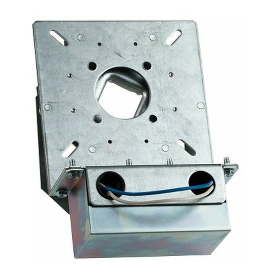
Gear Box
Brake Solenoid
with cover
BRAKE KIT
•
Brake Hub Assembly
•
Adhesive
Set Screw
Key
Gear Box
Shaft
1/8" minimum
(.32 cm)
Brake Hub
Brake Mounting Plate
Locking Ring
Brake Disc
Brake Pressure Plate
Publicidad

Manuales relacionados para LiftMaster K71-BPH-1


Resumen de contenidos para LiftMaster K71-BPH-1
- Página 1 BRAKE KIT MODELS K71-B1PH-1, K71-B3PH-1 & K71-B575-1 The kit will provide up to 5 lb-ft of braking torque at 1725 RPM. Model K71-B1PH-1 . . . For SL585501U, SL585101U, SL585151U, SL595101U, & SL595151U single phase gate operators To prevent possible SERIOUS INJURY or DEATH, disconnect electric power to operator BEFORE installing.
- Página 2 MODEL SL595 INSTALL THE NEW BRAKE KIT REMOVE EXISTING BRAKE KIT 1. Install the new key on the gear box shaft. 1. Disconnect power to operator. 2. Place the new brake hub on the gear box shaft. Position the 2. Unbolt the gear box and motor and slide to the right. brake hub 1/8"...
- Página 3 NÉCESSAIRE DE FREIN MODÈLES K71-B1PH-1, K71-B3PH-1 ET K71-B575-1 Le nécessaire fournira jusqu’à 5 lb-pi de couple de freinage à un régime de 1 725 tr/min. Modèle K71-B1PH-1 . . Pour actionneurs de barrière monophasés, Pour éviter de GRAVES BLESSURES ou la MORT, débrancher modèles SL585501U, SL585101U, SL585151U, SL595101U, et l’alimentation électrique à...
- Página 4 MODÈLE SL595 ENLEVER LE NÉCESSAIRE DE FREIN EXISTANT INSTALLER LE NÉCESSAIRE DE FREIN NEUF 1. Débrancher l’alimentation électrique à l’actionneur. 1. Installer la clé neuve sur l’axe du boîtier d’engrenage. 2. Déboulonner le boîtier d’engrenage et le moteur et les faire 2.
-
Página 5: Contenido De La Caja
JUEGO DE FRENO MODELOS K71-B1PH-1, K71-B3PH-1 Y K71-B575-1 El juego brindará hasta 5 libras-pie de torque de frenado a 1725 ADVERTENCIA RPM. Modelo K71-B1PH-1 . Para los operadores de portón monofásicos Para evitar una posible LESIÓN GRAVE o la MUERTE, SL585501U, SL585101U, SL585151U, SL595101U, y SL595151U desconecte la energía eléctrica del operador ANTES de la instalación. - Página 6 MODELO SL595 INSTALAR EL NUEVO JUEGO DE FRENO RETIRAR EL JUEGO DE FRENO EXISTENTE 1. Instalar la llave nueva en el eje de la caja de engranajes. 1. Desconectar la energía eléctrica del operador. 2. Colocar el cubo de freno nuevo en el eje de la caja de 2.
- Página 8 © 2016 LiftMaster All Rights Reserved Tous droits réservés 01-38338 Todos los derechos reservados...