Festo CPV Instrucciones Para El Usuario
Ocultar thumbs
Ver también para CPV:
- Breve descripción (74 páginas) ,
- Manual del usuario (63 páginas) ,
- Manual de instrucciones (2 páginas)
Tabla de contenido
Publicidad
Idiomas disponibles
Idiomas disponibles
Enlaces rápidos
Publicidad
Tabla de contenido

Manuales relacionados para Festo CPV


Resumen de contenidos para Festo CPV
- Página 1 Compact Performance Kurz− beschreibung Brief description CPV−Ventilinsel mit Direkt− anschluss CPV...−GE−CO3−8 CPV valve terminal with direct connection Type CPV...−GE−CO3−8 Deutsch English Español Français Italiano Svenska 706 028 0709NH...
- Página 2 ......... . . Edition: 0709NH Original: de © (Festo SE & Co. KG, D 73726 Esslingen, Germany, 2007) Internet: http://www.festo.com E−Mail: service_international@festo .com Festo CPV...−GE−CO3−8 0709NH...
- Página 3 Benutzerhinweise Deutsch Die CPV−Ventilinsel mit Feldbus−Direktanschluss (CPV Direct) ist ausschließlich für den Einsatz als Teilnehmer am Feldbus CANopen bestimmt. Hierbei sind die angegebenen Grenzwerte der technischen Daten einzuhalten. Ausführliche Informationen finden Sie in Beschreibung P.BE−CP−CO3−... Warnung S Schalten Sie die Spannung aus, bevor Sie Steckver binder zusammen stecken oder trennen (Funktions schädigung).
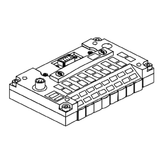
- Página 4 Schalterabdeckung (abgenommen) 2.1 Pinbelegung des Spannungsversor gungs− Anschlusses 2 M12−Anschluss Pin−Nr. 1. DC 24 V Betriebsspannung Elektronik und Eingänge 2. DC 24 V Lastspannung Ventile 3. 0 V 4. Erdungsanschluss Bei angeschlossenen Modulen am Erweiterungsanschluss Festo CPV...−GE−CO3−8 0709NH Deutsch...
- Página 5 2.3 Pinbelegung Feldbusanschluss (Sub−D−9 Stecker) Sub−D−9 Stecker Pin−Nr. Festo Sub−D−Buchse auf CPV Insel 2. CAN_L 3. 0 V Bus 5. CAN−Schirm Kabelschelle 7. CAN_H 9. 24 V Bus Typ FBS−SUB−9−BU−2x4POL (Zubehör) Details finden Sie in der Beschreibung P.BE−CP−CO3−... Festo CPV...−GE−CO3−8 0709NH Deutsch...
- Página 6 Als Zubehör erhalten Sie folgende Anschlüsse von Festo: M12 Adapter: Typ FBA−2−M12−5POL Schraubklemmen−Adapter: Typ FBA−1−SL−5POL dazu Klemmleiste: Typ FBSD−KL−2x5POL 2.4 Pinbelegung Feldbusanschluss (M12−Adapter) M12−Adapter Pin−Nr. 1. Schirm 2. 24 VDC Bus (max. 4 A) 3. 0 V Bus 4. CAN_H 5.
-
Página 7: Konfiguration
Automatische Erkennung durchführen (siehe Abschnitt 5.2, nicht in Werkzeug wechsel−Konfiguration erforderlich). 6. Schalterabdeckung montieren. 7. Ist die CPV Direct erster oder letzter Teilnehmer in ei nem Feldbussegment, muss ein Abschlusswiderstand zwischen die Feldbusleitungen montiert werden (120 , 0,25 W). - Página 8 Kodierte Eingabe Beispiel: Stationsnummer: 38 2 + 4 + 32 = 4.2 Feldbus−Baudrate einstellen (2fach DIL−Schalter) Stellen Sie die Baudrate mit den Schalterelementen 1 und 2 des 2fach−DIL−Schalters ein. 125 kBaud 250 kBaud 500 kBaud 1000 kBaud Festo CPV...−GE−CO3−8 0709NH Deutsch...
- Página 9 4.3 Konfigurations−Modus einstellen (8fach DIL) Stellen Sie den Konfigurations−Modus mit dem Schalter element 8 des 8fach−DIL−Schalters ein. Konfigurations−Modus Stellung der Schalterelemente Normal−Modus DIL 2.8 = off Werkzeugwechsel− DIL 2.8 = on Konfiguration Festo CPV...−GE−CO3−8 0709NH Deutsch...
- Página 10 Das kann nur im Normal−Modus erfolgen. 2fach DIL−Schalter, Schalterelement 1 2 zum Einstellen der CANopen Baudrate SAVE−Taste für CPI−System 8fach DIL−Schalter, Schalterelement 1 7 zum Einstellen der CANopen Busadresse (Node−ID) 8fach DIL−Schalter, Schalterelement 8 zum Einstellen des Konfiguartions−Modus (Werkzeugwechsel−Konfiguration) Festo CPV...−GE−CO3−8 0709NH Deutsch...
- Página 11 5.1 Erweiterung der CPV Direct Am CPI−Erweiterungsanschluss können Sie CPI−/CP− Module und/oder CP−Ventilinseln mit und ohne erweiterte Funktionalität anschließen. Die Ventilinsel CPV−CO3 ist CPI−Master. Beachten Sie die Regeln für die Erweiterung in Abschnitt 8 Technische Daten" und der Beschreibung P.BE−CPV−CO3−... 5.2 Strangbelegung speichern Voraussetzung: Module im CP−Strang korrekt angeschlossen, Spannungs...
- Página 12 Adressierung Für die Adressierung der CPV Direct gilt allgemein: 1. Eine CPV−Ventilinsel belegt immer 16 Ausgangs− adressen. Ein CP−Ventilplatz belegt zwei Adressen: niederwertige Adresse = Vorsteuermagnet 14 höherwertige Adresse = Vorsteuermagnet 12 2. CP−Ventilinseln, elektrische Ausgangs− oder Eingangs module am CPI−Erweiterungsstrang belegen je nach Ausführung 8, 16,...
- Página 13 Prüfen der Netzwerkverbindung blinkt schnell rot: Kommunikationsfehler, Steuerung im Stopp−Zustand leuchtet rot: Ausfall Spannungsversor gung, Prüfen der Netzwerkverbindung Sonstige Fehler blinkt schnell: Konfigurationsfehler CP−Strang (rot) blinkt langsam: Modul im CP−Strang hat Diagnosefall leuchtet: Modulausfall im CP−Strang Festo CPV...−GE−CO3−8 0709NH Deutsch...
-
Página 14: Technische Daten
EMV Störfestigkeit è www.festo.com CPI−Strangerweiterung Leitungslänge max. 10 m Module (Regeln) max. 4 Module mit zusammen max. 32 E und 32 A am CP−Strang Stromaufnahme max. 1,6 A bei 24 V Weitere Regeln in der Beschreibung P.BE−CP−CO3−... Festo CPV...−GE−CO3−8 0709NH Deutsch... - Página 15 26,4 V Stromaufnahme Summe aller eingeschalteten CP−Magnetventile; siehe Beschreibung CP Pneumatik" Restwelligkeit 4 Vss (innerhalb Toleranz) Galvanische Trennung Busschnittstelle opto−entkoppelt Ventile siehe Pneumatik−Beschreibung P.BE−CPV−... Ausführliche Informationen über die CPV Direct CO3 erhalten Sie in der Beschreibung P.BE−CP−CO3−... Festo CPV...−GE−CO3−8 0709NH Deutsch...
- Página 16 Festo CPV...−GE−CO3−8 0709NH Deutsch...
- Página 17 User instructionsEnglish The CPV valve terminal with field bus direct connection (CPV Direct) is intended exclusively for use as a slave on the field bus CANopen. The maximum values specified in the section Technical specifications" must be observed here. Detailed informa tion can be found in the manual P.BE−CP−CO3−...
- Página 18 M12 connection Pin no. 1. 24 V DC operating voltage for the electronics and inputs 2. 24 V DC load voltage for valves 3. 0 V 4. Earth connection On the extension connection of connected modules Festo CPV...−GE−CO3−8 0709NH English...
- Página 19 Pin no. Festo Sub−D CPV valve terminal socket 2. CAN_L 3. 0 V bus 5. CAN screening/shield Cable clip 7. CAN_H 9. 24 V bus Type FBS−SUB−9−BU−2x4POL (accessory) Detailed information can be found in the manual P.BE−CP−CO3−... Festo CPV...−GE−CO3−8 0709NH English...
- Página 20 2.5 Pin assignment (screw terminal adapter (IP20) Screw terminal adapter Pin no. 1. 0 V bus 2. CAN_L 3. Screening/shield 4. CAN_H 1 2 3 4 5 5. 24 V DC bus (max. 4 A) Festo CPV...−GE−CO3−8 0709NH English...
-
Página 21: Configuration
Configuration Caution The CPV Direct contains electronically sensitive compo nents. The CPV Direct will be damaged if you touch the contact surfaces of the plug connectors or if you do not observe the regulations for handling electrostatically sensitive components. Proceed with the configuration as follows: 1. - Página 22 2 + 4 + 32 = 4.2 Setting the field bus baud rate (2−element DIL switch) Set the baud rate with switch elements 1 and 2 of the 2−element DIL switch. 125 kBaud 250 kBaud 500 kBaud 1000 kBaud Festo CPV...−GE−CO3−8 0709NH English...
- Página 23 (8−element DIL switch) Set the configuration mode with switch element 8 of the 8−element DIL switch. Configuration mode Position of the switch elements Normal mode DIL 2.8 = off Tool change DIL 2.8 = on configuration Festo CPV...−GE−CO3−8 0709NH English...
- Página 24 CANopen baud rate SAVE button for CPI system 8−element DIL switch, switch elements 1 7 for setting the CANopen bus address (node ID) 8−element DIL switch, switch element 8 for setting the configuration mode (tool change configuration) Festo CPV...−GE−CO3−8 0709NH English...
- Página 25 The modules in the CP string must be connected correctly, the power supply must be switched off. 1. Switch on the power supply for the CPV Direct and, if applicable, for the CPI/CP modules/valve terminals. If the string assignment is new or has been modified, the LED P will flash.
- Página 26 Addressing The following applies in general for addressing the CPV Direct: 1. A CPV valve terminal always occupies 16 output addresses. A CP valve location occupies two addresses: lower−value address = pilot solenoid 14 higher−value address = pilot solenoid 12 2.
-
Página 27: Diagnosis Via Leds
Supply voltage failed, check the mains connection Other faults flashes fast: Configuration fault in CP string ( d) (red) flashes slowly: Module in the CP string has diagnostic case lights up: Module failure in the CP string Festo CPV...−GE−CO3−8 0709NH English... -
Página 28: Technical Specifications
Cable length max. 10 m Modules (regulate) max. 4 modules with together max. 32 inputs and 32 outputs on the CP string Current consumption max. 1.6 A at 24 V Further rules in the manual P.BE−CP−CO3−... Festo CPV...−GE−CO3−8 0709NH English... - Página 29 CP solenoid valves; see manual CP pneumatics" Residual ripple 4 Vpp (within tolerance) Electrical isolation bus interface opto−decoupled Valves see Pneumatics manual P.BE−CPV−... Detailed information on the CPV Direct CO3 can be found in the manual P.BE−CP−CO3−... Festo CPV...−GE−CO3−8 0709NH English...
- Página 30 Festo CPV...−GE−CO3−8 0709NH English...
-
Página 31: Español
Instrucciones para el usuarioEspañol El terminal de válvulas CPV con conexión directa a bus de campo (CPV Direct) está diseñado exclusivamente para ser utilizado como participante en el bus de campo CANopen. Deben observarse los valores máximos indicados en la sección Especificaciones técnicas". -
Página 32: Conexiones Y Elementos De Indicación
1. Tensión de funcionamiento 24 V DC para la electrónica y las entradas 2. Tensión de carga DC 24 V para las válvulas 3. 0 V 4. Conexión a tierra Si hay módulos conectados a la conexión de ampliación Festo CPV...−GE−CO3−8 0709NH Español... -
Página 33: Ejemplo De Conexión Con Unidad Pelv Para La Red Y Compensación De Potencial
Pin n° Zócalo Sub−D de 9 pines en Festo terminal CPV 2. CAN_L 3. 0 V Bus 5. Apantallamiento CAN Sujetacables 7. CAN_H 9. 24 V Bus Tipo FBS−SUB−9−BU−2x4POL (accesorios) Hallará información detallada en el manual P.BE−CP−CO3−... Festo CPV...−GE−CO3−8 0709NH Español... - Página 34 Como accesorios recibirá las siguientes conex. de Festo: adaptador M12: tipo FBA−2−M12−5POL adapt. de bornes atornillados: tipo FBA−1−SL−5POL y la regleta de bornes: tipo FBSD−KL−2x5POL 2.4 Asignación de pines de la conexión al bus de campo (adaptador M12) Adaptador M12 Pin n°...
-
Página 35: Configuración
6. Montar la tapa de interruptores. 7. Si el CPV Direct es el primer o último participante en un segmento de bus de campo deberá montarse una resistencia de terminación entre los cables del bus de campo (120 , 0,25 W). -
Página 36: Ajuste De La Velocidad De Transmisión Del Bus De Campo (Interruptor Dil De 2 Elementos)
4.2 Ajuste de la velocidad de transmisión del bus de campo (interruptor DIL de 2 elementos) Ajuste la velocidad de transmisión con los elementos 1 y 2 del interruptor DIL de 2 elementos. 125 kBaud 250 kBaud 500 kBaud 1000 kBaud Festo CPV...−GE−CO3−8 0709NH Español... -
Página 37: Ajuste Del Modo De Configuración (Dil De 8 Elementos)
Ajuste el modo de configuración con el elemento 8 del interruptor DIL de 8 elementos. Modo de configuración Ajuste de los elementos del interruptor Modo normal DIL 2.8 = off Configuración de cambio DIL 2.8 = on de herramienta Festo CPV...−GE−CO3−8 0709NH Español... -
Página 38: Reconocimiento De La Ampliación Cpi Con La Tecla Save
Interruptor DIL de 8 elementos, elementos 1 a 7 para ajustar la dirección de bus de CANopen (ID del nodo) Interruptor DIL de 8 elementos, elemento 8 para ajustar el modo de configuración (configuración de cambio de herramienta) Festo CPV...−GE−CO3−8 0709NH Español... -
Página 39: Ampliación Cpi Y Tecla Save
En la conexión de ampliación CP se pueden conectar módulos CPI/CP y/o terminales de válvulas CP con y sin funciones ampliadas. El terminal de válvulas CPV−CO3 es un master CPI. Observe las reglas para la ampliación en la sección 8 Especificacio nes técnicas" y en el manual P.BE−CPV−CO3−... -
Página 40: Asignación De Direcciones
Asignación de direcciones Para el direccionamiento del CPV Direct en general se aplica lo siguiente: 1. Un terminal de válvulas CPV ocupa siempre 16 direcciones de salida. Una posición de válvula CP ocupa dos direcciones: dirección de valor bajo = bobina del pilotaje 14 dirección de valor alto = bobina del pilotaje 12... -
Página 41: Diagnóstico Mediante Leds
CP carga (pin 2) carga (pin 2) Intermitente rápido: subtensión en la válvulas del CPV Direct Apagado: no hay tensión de carga Fallo del bus Intermitente rápido verde: conectado, (rojo/ control en estado de Stop... -
Página 42: Especificaciones Técnicas
Módulos (reglas) máx. 4 módulos con un total de 32 I y 32 O como máx. en el ramal CP Consumo de corriente máx. 1,6 A (con 24 V) Hallará más reglas en el manual P.BE−CP−CO3−... Festo CPV...−GE−CO3−8 0709NH Español... - Página 43 CP conectadas; véase el manual Neumática CP" Ondulación residual 4 Vpp (dentro de la tolerancia) Separación galvánica Interface bus opto−desacoplado Válvulas véase el manual de neumática P.BE−CPV−... Hallará información detallada sobre el CPV Direct CO3 en el manual P.BE−CP−CO3−... Festo CPV...−GE−CO3−8 0709NH Español...
- Página 44 Festo CPV...−GE−CO3−8 0709NH Español...
-
Página 45: Remarques Pour L'uTilisateur
Remarques pour l’utilisateur Français Le terminal de distributeur CPV avec raccord direct pour bus de terrain (CPV Direct) doit être uniquement utilisé en tant qu’abonné sur le bus de terrain CANopen. Les valeurs maximales indiquées concernant les caractéris tiques techniques doivent être respectées. Pour de plus amples informations se reporter au manuel P.BE−CP−CO3−... - Página 46 Connecteur M12 Broche n° 1. Alimentation de l’électronique et des entrées 24 V CC 2. Alimentation principale 24 V CC des distrib. 3. 0 V 4. Borne de terre Pour les modules connectés sur le connecteur d’extension Festo CPV...−GE−CO3−8 0709NH Français...
- Página 47 Broche n° Connecteur femelle sur terminal CPV Sub−D Festo 2. CAN_L 3. Bus 0 V 5. Blindage CAN Serre−câble 7. CAN_H 9. Bus 24 V Type FBS−SUB−9−BU−2x4POL (Accessoires) Pour plus de détails se reporter au manuel P.BE−CP−CO3−... Festo CPV...−GE−CO3−8 0709NH Français...
- Página 48 Parmi les accessoires, Festo fournit les connecteurs suivants : Adaptateur M12 : type FBA−2−M12−5POL Adaptateur pour bornes à vis : type FBA−1−SL−5POL avec bornier : type FBSD−KL−2x5POL 2.4 Affectation des broches du connecteur de bus de terrain (adaptateur M12) Adaptateur M12 Broche n°...
- Página 49 6. Monter le cache des interrupteurs. 7. Si le CPV Direct est le premier ou le dernier abonné dans un segment de bus de terrain, une résistance de terminaison doit être montée entre les câbles de bus de terrain (120 , 0,25 W).
- Página 50 4.2 Réglage de la vitesse de transmission du bus de terrain (interrupteur DIL à 2 commutateurs) Régler la vitesse de transmission à l’aide des commuta teurs 1 et 2 de l’interrupteur DIL à 2 commutateurs. 125 kbauds 250 kbauds 500 kbauds 1000 kbauds Festo CPV...−GE−CO3−8 0709NH Français...
- Página 51 Régler le mode de configuration à l’aide du commutateur 8 de l’interrupteur DIL à 8 commutateurs. Mode de configuration Position des commutateurs Mode normal DIL 2.8 = off Configuration de DIL 2.8 = on changement d’outil Festo CPV...−GE−CO3−8 0709NH Français...
- Página 52 Touche SAVE destinée au système CPI Interrupteur DIL à 8 commutateurs, commutateurs 1 destinés au réglage de l’adresse de bus du CANopen (Node−ID) Interrupteur DIL à 8 commutateurs, commutateur 8 destiné au réglage du mode de configuration (configuration de changement d’outil) Festo CPV...−GE−CO3−8 0709NH Français...
- Página 53 Condition : Module sur branche CP correctement raccordé, alimenta tion électrique coupée. 1. Mettre le CPV Direct et si nécessaire les terminaux de distributeurs/modules CPI/CP sous tension. Si une nouvelle affectation des branches a été créée ou si l’affectation des branches a été modifiée, la LED P clignote.
- Página 54 Adressage Pour l’adressage du CPV Direct, tenir compte des points suivants : 1. Un terminal de distributeurs CPV occupe toujours 16 adresses de sortie. Un emplacement de distributeurs CP utilise deux adresses : adresse de poids faible = bobine de pilotage 14...
- Página 55 Autre erreur clignote rapidement : erreur de configuration de la branche CP (rouge) clignote lentement : le module sur la branche CP rencontre un cas de diagnostic allumée : défaillance module sur branche CP Festo CPV...−GE−CO3−8 0709NH Français...
-
Página 56: Caractéristiques Techniques
10 m max. Modules (règles) max. 4 modules utilisant au total max. 32 E et 32 S sur la branche CP Consommation électrique max. 1,6 A à 24 V Le manuel d’utilisation P.BE−CP−CO3−... contient d’autres règles. Festo CPV...−GE−CO3−8 0709NH Français... - Página 57 Pneumatique CP" Ondulation résiduelle 4 Vcc (dans la tolérance) Séparation galvanique Interface de bus par optocoupleur Distributeurs voir manuel Pneumatique P.BE−CPV−... Vous trouverez de plus amples informations sur le CPV Direct CO3 dans le manuel d’utilisation P.BE−CP−CO3−... Festo CPV...−GE−CO3−8 0709NH Français...
- Página 58 Festo CPV...−GE−CO3−8 0709NH Français...
-
Página 59: Italiano
Indicazioni per l’utilizzatoreItaliano L’unità di valvole CPV con collegamento diretto al fieldbus (CPV Direct) è destinata esclusivamente all’impiego quale utenza del fieldbus CANopen. A questo proposito osservare i valori limite specificati nei dati tecnici. Per informazioni più dettagliate fare riferi mento alla descrizione P.BE−CP−CO3−... - Página 60 2 Connettore M12 N. pin 1. tensione d’esercizio 24 VCC elettronica e ingressi 2. tensione di carico 24 VCC valvole 3. 0 V 4. connessione messa a terra Con i moduli collegati al connettore di espansione Festo CPV...−GE−CO3−8 0709NH Italiano...
- Página 61 Connettore femmina su unità CPV Sub−D Festo 2. CAN_L 3. bus 0 V 5. schermo CAN fascetta serracavi 7. CAN_H 9. bus 24 V Tipo FBS−SUB−9−BU−2x4POL (vedi Accessori") Per informazioni più dettagliate fare riferimento alla descrizione P.BE−CP−CO3−... Festo CPV...−GE−CO3−8 0709NH Italiano...
- Página 62 Tra gli accessori Festo sono disponibili i seguenti connettori: Adattatore M12: tipo FBA−2−M12−5POL Adattatore per morsetti a vite: tipo FBA−1−SL−5POL oltre alla morsettiera: tipo FBSD−KL−2x5POL 2.4 Occupazione dei pin connessione fieldbus (adattatore M12) Adattatore M12 N. pin 1. schermo 2. 24 VCC bus (max. 4 A) 3.
- Página 63 6. Montare la placchetta di copertura degli interruttori. 7. Montare una resistenza terminale fra i conduttori fieldbus se l’unità CPV Direct è la prima o l’ultima utenza in un segmento (120 , 0,25 W). Avvertenza S Verificare la sicurezza di funzionamento dell’impianto in caso di emergenza.
- Página 64 2 + 4 + 32 = 4.2 Impostazione della baudrate fieldbus (interruttore DIL a 2 elementi) Impostare la baudrate con gli elementi 1 e 2 dell’interrut tore DIL a 2 elementi. 125 kBaud 250 kBaud 500 kBaud 1000 kBaud Festo CPV...−GE−CO3−8 0709NH Italiano...
- Página 65 (interruttore DIL a 8 elementi) Impostare il modo di configurazione con l’elemento 8 dell’interruttore DIL a 8 elementi. Modo di configurazione Posizione degli elementi Modo normale DIL 2.8 = off Configurazione del cambio DIL 2.8 = on tool Festo CPV...−GE−CO3−8 0709NH Italiano...
- Página 66 Tasto SAVE per sistema CPI Interruttore DIL a 8 elementi, elementi 1 7 per l’impostazione dell’indirizzo di bus CANopen (Node−ID) Interruttore DIL a 8 elementi, elemento 8 per l’impostazione del modo di configurazione (configurazione del cambio tool) Festo CPV...−GE−CO3−8 0709NH Italiano...
- Página 67 Sul connettore di espansione CPI si possono collegare moduli CPI/CP e/o unità di valvole CP con o senza funzionalità ampliata. L’unità di valvole CPV−CO3 è un master CPI. Osservare le prescrizioni per l’espansione riportate al punto 8 Dati tecnici" e nella descrizione P.BE−CPV−CO3−...
- Página 68 Indirizzamento Per l’indirizzamento dell’unità di valvole CPV Direct valgono le seguenti regole generali: 1. Una unità di valvole CPV occupa sempre 16 indirizzi di uscita. Un posto valvola CP occupa due indirizzi: indirizzo meno significativo = solenoide pilota 14 indirizzo più significativo = solenoide pilota 12 2.
-
Página 69: Diagnosi Tramite Led
CP (rosso) lampeggia lentamente: diagnosticare il modulo nella linea CP acceso: disfunzione del modulo nella linea CP Festo CPV...−GE−CO3−8 0709NH Italiano... -
Página 70: Dati Tecnici
10 m moduli (prescrizioni) max. 4 moduli con insieme max. 32 I e 32 O sulla linea CP assorbimento di corrente max. 1,6 A a 24 V Per altre prescrizioni fare riferimento alla descrizione P.BE−CP−CO3−... Festo CPV...−GE−CO3−8 0709NH Italiano... - Página 71 Ondulazione residua 4 Vss (entro i valori di tolleranza) Isolamento galvanico interfaccia bus a disaccoppia mento optoelettronico Valvole vedi descrizione della parte pneumatica P.BE−CPV−... Per informazioni dettagliate sull’unità di valvole CPV Direct CO3 vedi la descrizione P.BE−CP−CO3−... Festo CPV...−GE−CO3−8 0709NH Italiano...
- Página 72 Festo CPV...−GE−CO3−8 0709NH Italiano...
-
Página 73: Svenska
Användaranvisningar Svenska CPV−ventilterminalen med direkt fältbussanslutning (CPV Direct) är endast avsedd för att användas som slav på fältbussen CANopen. Följ de gränsvärden som anges under Tekniska data. Utförligare information finns i manualen P.BE−CP−CO3−... Varning S Koppla från spänningen innan kontakter ansluts eller lossas (risk för funktionsskada). - Página 74 CPI−systemslinga Omkopplarskydd (lossat) 2.1 Kontaktkonfiguration för anslutning av spänningsmatning 2 M12−anslutning Stiftnr. 1. DC 24 V matningsspänning elektronik och ingångar 2. DC 24 V matningsspänning ventiler 3. 0 V 4. Jordanslutning Vid anslutna moduler på systemslingan Festo CPV...−GE−CO3−8 0709NH Svenska...
- Página 75 2.3 Kontaktkonfiguration för fältbussanslutning (9−polig D−sub−hankontakt) 9−polig D−sub−hankontakt Stiftnr. Festo D−sub− på CPV−terminal honkontakt 2. CAN_L 3. 0 V−buss 5. CAN−skärm Kabelklämma 7. CAN_H 9. 24 V−buss Typ FBS−SUB−9−BU−2x4POL (tillbehör) Utförligare information finns i manualen P.BE−CP−CO3−... Festo CPV...−GE−CO3−8 0709NH Svenska...
- Página 76 Följande anslutningar bifogas som tillbehör från Festo: M12 adapter: FBA−2−M12−5POL Skruvplintsadapter: FBA−1−SL−5POL därtill fjäderplint: FBSD−KL−2x5POL 2.4 Kontaktkonfiguration för fältbussanslutning (M12−adapter) M12−adapter Stiftnr. 1. Skärm 2. 24 VDC−buss (max. 4 A) 3. 0 V−buss 4. CAN_H 5. CAN_L Bus Out Bus In Blindplugg för anslutningar...
- Página 77 CPI−systemslingan: Utför automatisk registrering (se avsnitt 5.2, ej nödvändigt vid utbytbar verktygskonfiguration). 6. Montera omkopplarskyddet. 7. Om CPV Direct är den första eller sista slaven i ett fältbussegment, måste ett termineringsmotstånd monteras mellan fältbusskablarna (120 , 0,25 W). Varning S Kontrollera vilka åtgärder du bör vidta för att försätta din anläggning i ett säkert tillstånd vid nödstopp.
- Página 78 Kodad inmatning Exempel: stationsnummer: 38 2 + 4 + 32 = 4.2 Ställa in fältbussens överföringshastighet (2−polig DIL−omkopplare) Ställ in överföringshastigheten med den 2−poliga DIL−omkopplarens strömställarelement 1 och 2. 125 kBit/s 250 kBit/s 500 kBit/s 1000 kBit/s Festo CPV...−GE−CO3−8 0709NH Svenska...
- Página 79 4.3 Ställa in konfigurationsläge (8−polig DIL) Ställ in konfigurationsläge med den 8−poliga DIL−omkopplarens strömställarelement 8. Konfigurationsläge Strömställarelementens läge Normalt läge DIL 2.8 = off Utbytbar verktygs DIL 2.8 = on konfiguration Festo CPV...−GE−CO3−8 0709NH Svenska...
- Página 80 CP−systemslingan. Detta gäller endast i normalt läge. 2−polig DIL−omkopplare, strömställarelement 1 för inställning av CANopen överföringshastighet SAVE−knappen för CPI−system 8−polig DIL−omkopplare, strömställarelement 1 för inställning av CANopen bussadress (Node−ID) 8−polig DIL−omkopplare, strömställarelement 8 för inställning av konfigurationsläge (utbytbar verktygskonfiguration) Festo CPV...−GE−CO3−8 0709NH Svenska...
- Página 81 5.2 Spara slingbeläggning Förutsättning: Modulerna är korrekt anslutna i CP−slingan och spänningsmatningen är frånkopplad. 1. Koppla till spänningsmatning för CPV Direct och eventuella CPI−/CP−moduler/ventilterminaler. Vid ny eller ändrad slingbeläggning blinkar LED P. 2. Håll SAVE−knappen intryck i minst 1 s.
- Página 82 Adressering För adressering av CPV Direct gäller i allmänhet: 1. En CPV−ventilterminal belägger alltid 16 utgångsadresser. En CP−ventilplats belägger två adresser: adress med lägre värde = styrmagnet 14 adress med högre värde = styrmagnet 12 2. CP−ventilterminaler och elektriska utgångs− eller ingångsmoduler på...
- Página 83 Blinkar långsamt i rött: kommunikationsfel, kontrollera nätverksanslutningen Blinkar snabbt i rött: kommunikationsfel, styrsystemet i stoppläge Lyser rött: Spänningsbortfall, kontrollera nätverksanslutningen Annat fel Blinkar snabbt: konfigurationsfel CP−slinga ( d) (röd) Blinkar långsamt: modul i CP−slingan har diagnosbortfall Lyser: modulbortfall i CP−slingan Festo CPV...−GE−CO3−8 0709NH Svenska...
-
Página 84: Tekniska Data
EMC−immunitet è www.festo.com CPI−slinga Kabellängd max 10 m Moduler (regler) max 4 moduler med sammanlagt max. 32 I och 32 O på CP−slingan Strömförbrukning max 1,6 A vid 24 V Ytterligare regler finns i manualen P.BE−CP−CO3−... Festo CPV...−GE−CO3−8 0709NH Svenska... - Página 85 26,4 V Strömförbrukning Summan av alla tillkopplade CP−magnetventiler finns i manualen CP−pneumatik" Tillåtet rippel 4 Vss (inom toleransen) Galvanisk isolering Bussgränssnittet opto−isolerat Ventiler Se pneumatikmanual P.BE−CPV−... Utförlig information om CPV Direct CO3 finns i manualen P.BE−CP−CO3−... Festo CPV...−GE−CO3−8 0709NH Svenska...
- Página 86 Festo CPV...−GE−CO3−8 0709NH Svenska...