Tabla de contenido
Publicidad
Idiomas disponibles
Idiomas disponibles
Enlaces rápidos
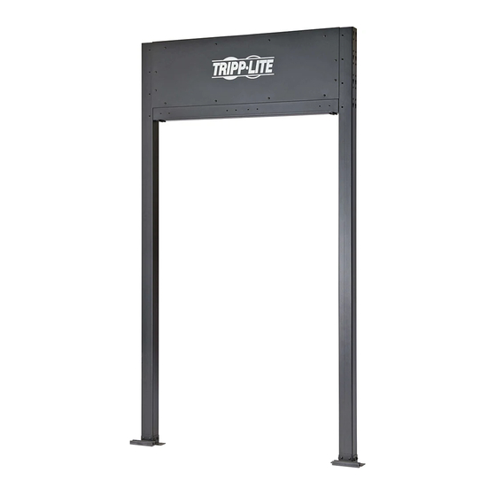
Installation Guide
Frame Kit
for Aisle Containment System
Model: SRCTMTFRM
Español 8 • Français 15 • Русский 22
Recommended Installation Order:
1. SRCTMTFRM Frame Kit
2. SRCTMTTLBM Beam Kit
3. SRCTMTSDD Sliding Double-Door Kit
4. SRCTMTCVR600, SRCTMTCVR750 Static Roof Panel Kit
5. SRCTMTR600SH, SRCTMTR600TL, SRCTMTR750SH, SRCTMTR750TL Adapter Riser Panels
1111 W. 35th Street, Chicago, IL 60609 USA • tripplite.com/support
Copyright © 2019 Tripp Lite. All rights reserved.
1
Publicidad
Tabla de contenido

Manuales relacionados para Tripp-Lite SRCTMTFRM


Resumen de contenidos para Tripp-Lite SRCTMTFRM
- Página 1 Aisle Containment System Model: SRCTMTFRM Español 8 • Français 15 • Русский 22 Recommended Installation Order: 1. SRCTMTFRM Frame Kit 2. SRCTMTTLBM Beam Kit 3. SRCTMTSDD Sliding Double-Door Kit 4. SRCTMTCVR600, SRCTMTCVR750 Static Roof Panel Kit 5. SRCTMTR600SH, SRCTMTR600TL, SRCTMTR750SH, SRCTMTR750TL Adapter Riser Panels 1111 W.
-
Página 2: Important Safety Instructions
Important Safety Instructions • This product should only be installed by someone of good mechanical ability, with basic building experience and a full understanding of the instructions in this guide. • Always use an assistant or mechanical lifting equipment to safely lift and position equipment. •... - Página 3 Installation Establish the perimeter for the containment system. Using a tape measure and chalk line, establish a perimeter for the containment system. • Make sure corners are square and at 90° • Width will depend on the number of racks to be installed Minimum Width: 96 in.
- Página 4 Installation Attach crossbeam connection brackets, vertical endcap mounting brackets and floor-mounting brackets to the frame uprights. Note: Do not mount the frame kit assembly to the floor at this time. For instructions on floor mounting the frame kit assembly, refer to the SRCTMTTLBM Beam Kit Installation Guide.
- Página 5 Installation Attach frame crossbars to the frame uprights. M6 x 16 Phillips Screw (x16) M6 External Tooth Lock Washer (x16) Crossbar Crossbar M6 x 16 Phillips Screw (x4) M5 x 10 Phillips Screw (x2) Make sure the door adjustment bracket points forward and toward the front side of the frame.
- Página 6 Installation Install the temporary frame support bracket at the base. Attaching the support bracket helps keep the frame end square. Do not remove until the SRCTMTTLBM Beam Kit has been installed (refer to the SRCTMTTLBM Installation Guide for more information). M6 External Tooth Lock M6 x 16 Phillips...
- Página 7 Installation To install the rear frame kit, repeat steps 2-5. Once the rear frame kit has been assembled, install the SRCTMTTLBM Beam Kit. Refer to the SRCTMTTLBM Installation Guide for more information. 1111 W. 35th Street, Chicago, IL 60609 USA • tripplite.com/support 19-04-158 93-391E_RevA...
-
Página 8: Juego De Bastidor Para Sistema De Contención Para Pasillo
Modelo: SRCTMTFRM English 1 • Français 15 • Русский 22 Orden Recomendado de Instalación: 1. Juego de Bastidor SRCTMTFRM 2. Juego de Viga SRCTMTTLBM 3. Juego de Puerta Deslizante Doble SRCTMTSDD 4. Juego de Panel Estático de Techo SRCTMTCVR600, SRCTMTCVR750 5. -
Página 9: Instrucciones De Seguridad Importantes
Instrucciones de Seguridad Importantes • Este producto debe ser instalado únicamente por una persona con habilidades mecánicas adecuadas, experiencia básica de construcción y que haya comprendido a cabalidad las instrucciones contenidas en esta guía. • Utilice siempre un ayudante o equipo de elevación mecánico para levantar y colocar el equipo con seguridad. •... -
Página 10: Instalación
Instalación Establezca el perímetro para el sistema de contención. Con una cinta métrica y una línea de tiza, establezca un perímetro para el sistema de contención. • Asegure que las esquinas estén a escuadra y a 90° • La anchura dependerá del número de racks que se instalarán Ancho Mínimo: 2442 mm [96"] (4 racks por lado usando ancho de rack estándar de 600 mm [24"]) Ancho Máximo: 3662 mm [144"] (6 racks por lado usando ancho de rack estándar de 600 mm [24"]) 3662 mm [144"] DE ANCHO MÁXIMO... - Página 11 Instalación Fije los soportes de conexión de travesaño, los soportes de instalación verticales de la tapa de extremo y los soportes para instalación en el suelo a los postes del bastidor. Nota: No instale el conjunto del juego de bastidor en el suelo en este momento. Para obtener instrucciones sobre la instalación en suelo del conjunto del juego de bastidor, consulte la Guía de Instalación del Juego de Viga SRCTMTTLBM.
- Página 12 Instalación Fije los travesaños del bastidor a los postes del bastidor. Tornillo Phillips M6 x 16 (x16) Arandela Dentada Externa de Seguridad M6 (x16) Travesaño Travesaño Tornillo Phillips M6 x 16 (x4) Tornillo Phillips M5 x 10 (x2) Asegúrese de que el soporte de ajuste de la puerta apunta hacia adelante y hacia la parte frontal del bastidor.
- Página 13 Instalación Instale el soporte de apoyo del bastidor temporal en la base. La fijación del soporte de apoyo ayuda a mantener a escuadra el extremo del bastidor. No lo retire hasta que se haya instalado el juego de viga SRCTMTTLBM (para obtener más información, consulte la Guía de Instalación de SRCTMTTLBM).
- Página 14 Instalación Para instala el juego de bastidor posterior, repita los pasos 2-5. Una vez montado el juego de bastidor trasero, instale el juego de viga SRCTMTTLBM. Para más información, refiérase a la Guía de Instalación del SRCTMTTLBM. 1111 W. 35th Street, Chicago, IL 60609 EE. UU. • tripplite.com/support 19-04-158 93-391E_RevA...
- Página 15 Modèle : SRCTMTFRM English 1 • Español 8 • Русский 22 Ordre d'installation recommandé : 1. Ensemble de cadre SRCTMTFRM 2. Ensemble de montant SRCTMTTLBM 3. Ensemble de porte double coulissante SRCTMTSDD 4. Ensemble de panneau de toit statique SRCTMTCVR600, SRCTMTCVR750 5.
-
Página 16: Consignes De Sécurité Importantes
Consignes de sécurité importantes • Ce produit ne devrait être installé que par une personne ayant de bonnes aptitudes en mécanique et une expérience de base en construction de même qu'une pleine connaissance des instructions du présent manuel. • Toujours faire appel à un assistant ou utiliser de l'équipement de levage mécanique pour soulever et mettre en place l'équipement. - Página 17 Installation Établir le périmètre pour le système d'enceinte. À l'aide d'un ruban à mesurer et d'un cordeau, établir un périmètre pour le système d'enceinte. • S'assurer que les coins sont à l'équerre et à 90°. • La largeur dépendra du nombre de bâtis à installer. Largeur minimum : 2 442 mm/96 po (4 bâtis par côté...
-
Página 18: Tabla De Contenido
Installation Fixer les supports de connexion de traverse, les supports de montage de capuchon vertical et les supports de montage au sol aux montants du cadre. Remarque : Ne pas monter l'ensemble de cadre au sol pour l'instant. Pour des instructions sur le montage au sol de l'ensemble de cadre, consulter le guide d'installation de la trousse de montant SRCTMTTLBM. -
Página 19: Vis Cruciforme M6 X
Installation Fixer les traverses du cadre aux montants du cadre. Vis cruciforme M6 x 16 (x16) Rondelle à dents externe M6 (x16) Traverse Traverse Vis cruciforme M6 x 16 Vis (x4) cruciforme M5 x 10 (x2) S'assurer que le support de réglage pointe vers l'avant et vers le côté... -
Página 20: Rondelle À Dents Externe M8 (X8)
Installation Installer le support de cadre temporaire à la base. Fixer le support aide à garder l'extrémité du cadre à l'équerre. Ne pas retirer avant d'avoir installé l'ensemble de montant SRCTMTTLBM (consulter le guide d'installation du SRCTMTTLBM pour plus d'informations). Rondelle à... - Página 21 Installation Pour installer l'ensemble de cadre arrière, répéter les étapes 2 à 5. Une fois l'ensemble de cadre arrière installé, installer l'ensemble de montant SRCTMTTLBM. Consulter le guide d'installation du SRCTMTTLBM pour plus d'informations. 1111 W. 35th Street, Chicago, IL 60609 USA • tripplite.com/support 19-04-158 93-391E_RevA...
-
Página 22: Руководство По Установке
системы защиты проходов Модель: SRCTMTFRM English 1 • Español 8 • Français 15 Рекомендуемый порядок установки: 1. Корпус в комплекте SRCTMTFRM 2. Балка в комплекте SRCTMTTLBM 3. Раздвижная двустворчатая дверца в комплекте SRCTMTSDD 4. Неподвижная верхняя панель в комплекте SRCTMTCVR600, SRCTMTCVR750 5. -
Página 23: Важные Указания По Технике Безопасности
Важные указания по технике безопасности • Установка данного изделия должна производиться только специалистом с достаточной технической квалификацией и базовыми навыками строительства, в полной мере понимающим смысл информации, изложенной в настоящем руководстве. • Для безопасного подъема и надлежащего размещения оборудования обязательно обращайтесь за помощью или пользуйтесь грузоподъемным оборудованием. •... - Página 24 Установка Наметьте периметр защитной системы. С помощью рулетки и мелового шнура наметьте периметр для установки защитной системы. • Необходимо убедиться в том, что намеченные углы образуют квадрат и имеют величину 90° • Ширина будет зависеть от количества шкафов, которые планируется установить Минимальная...
- Página 25 Установка Прикрепите кронштейны для соединения внешних балок, кронштейны для крепления вертикального торца и кронштейны для крепления к полу к вертикальным стойкам корпуса. Примечание. На данном этапе не следует крепить собранный корпус к полу. Указания по креплению собранного корпуса к полу изложены в Руководстве по установке балки в комплекте...
- Página 26 Установка Прикрепите поперечные рейки корпуса к его вертикальным стойкам. Винт M6 x 16 с крестообразным шлицем (16 шт.) Внешняя зубчатая пружинная шайба M6 (16 шт.) Поперечная рейка Поперечная рейка Винт M6 x 16 с крестообразным шлицем (4 шт.) Винт M5 x 10 с крестообразным...
- Página 27 Установка Установите временный опорный кронштейн для поддержки корпуса у его основания. Крепление опорного кронштейна помогает удерживать квадратную форму корпуса. Не снимайте его до тех пор, пока не будет установлена балка SRCTMTTLBM (более подробная информация представлена в Руководстве по установке изделия мод. SRCTMTTLBM). Внешняя...
- Página 28 Установка Для установки заднего корпуса повторите шаги 2-5. После сборки поставленного в комплекте корпуса установите балку SRCTMTTLBM. Более подробная информация представлена в руководстве по установке изделия SRCTMTTLBM. 1111 W. 35th Street, Chicago, IL 60609 USA • tripplite.com/support 19-04-158 93-391E_RevA...