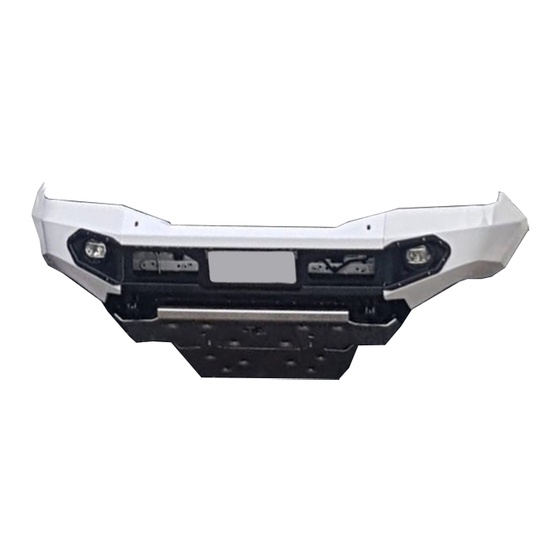
Resumen de contenidos para RHINO RPDE3D-VX 200 FL
- Página 1 . r h i n o 4 x 4 . c o m . a r INSTRUCCIONES DE ARMADO RPDE3D-VX 200 FL INSTALLATION INSTRUCTION MANUAL RPDE3D-VX 200 FL I N D U S T R I A A R G E N T I N A...
- Página 3 Before commencing with the installation it is important that you read and understand these installation instructions, if you need any technical advice please contact your closest Rhino 4x4 Dealer WELCOME TO THE RHINO 4X4 TEAM! ESPAÑOL Gracias por elegir equipar su vehiculo con nuestro producto.
-
Página 4: Bloque I : Preparar Soportes Del Chasis
BLOQUE I : PREPARAR SOPORTES DEL CHASIS BLOCK I: PREPARE CHASIS'S BRACKETS PASO 1 STEP 1 Antes de sacar el paragolpes original del vehículo Before you remove the original bumper, you must asegurarse de desconectar los componentes eléctricos disconnect electric components (foglights, parking (faros antiniebla, sensores de estacionamiento, etc) y aids, etc) and keep the wirings to reinstall them later. -
Página 5: Step 10 Paso
Montar los soportes frontales izquierdo y derecho del Fit the left and rigth Rhino bumper mounting brackets bumper Rhino en las puntas del chasis tal como lo muestra to the front chassis end as shown below. Tight the el dibujo. Ajustar los tornillos. - Página 6 PASO 3 STEP 3 Colocar la bandeja portamalacate sobre los soportes del Mount the winch cradle on the brackets from Paso 2. No ajuste los tornillos. Instale el malacate si fuera Step 2. Keep the bolts loosely. Install winch if it necesario.
- Página 7 STEP 4 PASO 4 Install the bumper support side brackets as per Instalar los soportes de las punteras cómo muestra el drawing. dibujo. KIT FIJACION / FASTENING KIT AR 10-1.5 x 30 Arandela / Washer D10 Tuerca / Nut 10 - 1.50 PASO 4 / STEP 4...
- Página 8 BLOQUE II : ARMADO DEL BUMPER BLOCK II: BUMPER ASSEMBLY STEP 5: PASO 5: Place the rubber strip on the wing's head lightedge. Colocar el burlete en el borde superior de la puntera. Leave 1.5 - 2 extra cm to the outer side for a better Dejar entre 1.5 y 2 cm extra entre la carrocería y la ending.
- Página 9 PASO 6 STEP 6 carcaza central superior sujetando a las Install the central case, insert it to the bumper wings as punteras del bumper como muestra la figura. Si su per drawing. If your vehicle counts with a sensor, connect vehiculo tiene sensor, conéctelo.
- Página 10 sobre la Antes lower to the winch wings Before aligned a 1-1.5 cm gap body and y el ajustar D 10...
- Página 11 STEP 8: PASO 8: Place the low cover and tight the bolts as per Coloque EL LOW COVER en las y ajuste los drawing. tornillos como muestra el dibujo KIT FIJACION / FASTENING KIT Allen Botón / Allen Button 6-100 x 15 Arandela/Washer D6 Tuerca / Nut 6-100 PASO 8 / STEP 8...
- Página 12 STEP 9: FOG LIGHTS ASSEMBLY PASO 9: ARMADO DE LOS FAROS ANTINIEBLA: Mount fog lights to plastic covers. Check that are Montar los faros antiniebla en los covertores plásticos. correctly aligned. Then adjust the foglight and mount Verificar que están correctamente alineados. Ajustar los the cover on the wings.
-
Página 13: Tabla De Contenido
PASO 10 STEP 10 Instale el chapon superior alineando los agujeros con los Mount the front skidplate aligning the holes with soportes del Paso 2. Luego coloque el soporte de brackets installed in step 2. Then install the chapon como muestran los dbujos. skidplate bracket as shown in the drawings. -
Página 14: Kit Fijacion / Fastening Kit
PASO 9 STEP 9 Instale el chapon inferior como muestran los dibujos y Install the lower bash plate as shown in the ajuste todos los tornillos. drawings and tight all the bolts. KIT FIJACION / FASTENING KIT ALLEN FRESADO 10 x 1.5 ALLEN FRESADO 8 x 1.25x 50 BUJE / BUSHING 24mm LLAVE CON TUERCA / WRENCH... - Página 15 STEP 12: NUMBER PLATE BRACKET PASO 12: PORTAPATENTE El portapatentes debe ser instalado en la carcasa An optional number plate bracket must be installed central, con el kit de fijación provisto. Cómo to the centre insert as per with the fastening kit alternativa, el portapatente puede ser instalado en la provided.
- Página 16 TERMINADO / FINISH...
- Página 17 LLAVE CON TUERCA/ AR 10-1.5 X 30 26u. ARANDELA/ WASHER D 8 WRENCH WITH NUT 8-1.25 PLACA ROSCADA/ ARANDELA / WASHER D 10 28u. TUERCA / NUT 8-1.25 THREADED PLATE 10-1.5 TORNILLO FRESADO/ ALLEN BOTÓN / 28u. TUERCA / NUT 10-1.50 COUNTERSUNK 8-1.25 x 30 ALLEN BUTTON 6-100 x 15 TORNILLO FRESADO/...
- Página 18 w w w . r h i n o 4 x 4 . c o m . a r MAIN OFFICE: AV. SABATTINI 2053 - CP X5014AUB - CORDOBA - ARGENTINA PHONE NUMBER: +54 0351 4563954 BRANCH OFFICE: AV. COLON 3655 - CP X5003DDH - CORDOBA - ARGENTINA PHONE NUMBER: +54 0351 4880522 "Designed and manufactured in Argentina"...
