Tabla de contenido
Publicidad
Idiomas disponibles
Idiomas disponibles
Enlaces rápidos
H-7619
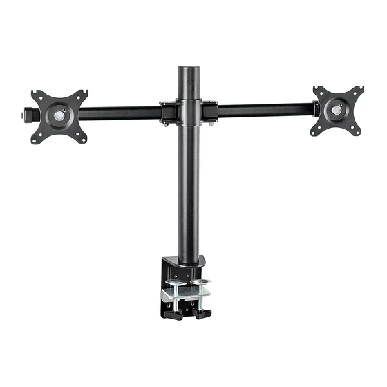
DUAL MONITOR MOUNT –
STANDARD
TOOLS NEEDED
Phillips Screwdriver
4 x 4 Allen Wrench (F)
5 x 5 Allen Wrench (G)
8
9
10
C
6
D
7
NOTE: Make sure the monitors have a VESA hole
pattern of 75 x 75 mm or 100 x 100 mm.
(See Figure 1)
NOTE: If the monitors are attached to fixed
bases, remove monitors from bases.
CAUTION! Be careful not to scratch the monitor
screen during installation.
PAGE 1 OF 12
3 x 3 Allen Wrench
6 x 6 Allen Wrench
(all included)
1
2
3
4
5
1-800-295-5510
uline.com
Two Person Assembly
Required
PARTS
#
DESCRIPTION
1
Tube Cover
2
Monitor Arm
3
Cable Clip
4
Tube
5
Clamp Mounting Bracket
6
Anti-Slip Foam
7
Clamp
8
Grommet Mounting Plate
9
Bottom Support
10
Grommet Bolt
A
M4 x 12 mm Bolt (Not Shown)
B
M5 x 12 mm Bolt (Not Shown)
C
M6 x 20 mm Bolt
D
M6 x 10 mm Bolt
E
Flat Washer (Not Shown)
SETUP
Figure 1
Para Español, vea páginas 5-8.
Pour le français, consulter les pages 9-12.
QTY.
2
1
4
1
1
2
1
1
1
1
8
8
3
2
16
75 x 75 mm or
100 x 100 mm
0521 IH-7619
Publicidad
Tabla de contenido

Resumen de contenidos para Uline H-7619
- Página 1 Para Español, vea páginas 5-8. Pour le français, consulter les pages 9-12. H-7619 1-800-295-5510 uline.com DUAL MONITOR MOUNT – STANDARD TOOLS NEEDED Phillips Screwdriver 3 x 3 Allen Wrench Two Person Assembly 4 x 4 Allen Wrench (F) Required 5 x 5 Allen Wrench (G)
- Página 2 ASSEMBLY CLAMP MOUNTING Anti-Slip Foam Tube M6 x 10 mm Bolts M6 x 20 mm Bolts 4 x 4 Allen Desk Wrench Mounting Holes Clamp Tighten 4 x 4 Allen Clamp Mounting Figure 2 Bracket Wrench 2. Apply anti-slip foam (6) to rings on clamp (7). Select NOTE: Clamp mount is compatible with desk the appropriate mounting holes based on thickness thickness of 3/4 –...
- Página 3 ASSEMBLY CONTINUED ATTACHING MONITOR ARM 3 x 3 Allen Figure 4 Wrench CAUTION! Make sure lever is tightly locked Place monitor arm (2) over tube (4) and choose desired height of monitor. (See Figure 4) before attaching monitor. 2. Flip lever on monitor arm to lock in place. Using 3.
- Página 4 2. Cables can be managed by running them through Allen wrench (G) to loosen bolts at hinges of monitor cable clips on monitor arm and through the arm and mounting plate as needed. (See Figure 6) openings in tube. 1-800-295-5510 uline.com PAGE 4 OF 12 0521 IH-7619...
-
Página 5: Soporte Doble Para Monitores - Estándar
H-7619 800-295-5510 uline.mx SOPORTE DOBLE PARA MONITORES – ESTÁNDAR HERRAMIENTAS NECESARIAS Desarmador Llave Allen de 3 x 3 Se Requiere Armar de Cruz Llave Allen de 4 x 4 (F) Entre Dos Personas Llave Allen de 5 X 5 (G) -
Página 6: Ensamble
ENSAMBLE INSTALACIÓN DE ABRAZADERAS Espuma Antiderrapante Tubo Pernos M6 x 10 mm Pernos M6 x 20 mm Llave Allen Escritorio de 4 x 4 Orificios para Abrazadera Ajuste Llave Allen Abrazadera para Instalación Diagrama 2 Soporte de Instalación de 4 x 4 NOTA: La abrazadera de instalación es compatible 2. -
Página 7: Continuación Del Ensamble
CONTINUACIÓN DEL ENSAMBLE FIJAR EL BRAZO PARA MONITOR Llave Allen Diagrama 4 de 3 x 3 ¡PRECAUCIÓN! Asegúrese de que la palanca 1. Coloque el brazo para monitor (2) sobre el tubo (4) y elija la altura del monitor deseada. (Vea Diagrama 4) esté... -
Página 8: Ajustar El Monitor Y Manejar El Cableado
Allen 5 x 5 mm (G) para aflojar los pernos de las para cableado del brazo del monitor y a través de bisagras del brazo del monitor y la placa de las aperturas del tubo. instalación como se requiera. (Vea Diagrama 6) 800-295-5510 uline.mx PAGE 8 OF 12 0521 IH-7619... -
Página 9: Outils Requis
H-7619 1-800-295-5510 uline.ca SUPPORT POUR DOUBLE MONITEUR – STANDARD OUTILS REQUIS Tournevis Clé Allen de 3 x 3 Montage à deux cruciforme Clé Allen de 4 x 4 (F) personnes requis Clé Allen de 5 x 5 (G) Clé Allen de 6 x 6 (tous inclus) PIÈCES... -
Página 10: Fixation Avec Collier De Serrage
MONTAGE FIXATION AVEC COLLIER DE SERRAGE Mousse antidérapante Tube Boulons M6 x 10 mm Boulons M6 x 20 mm Clé Allen Bureau de 4 x 4 Trous de fixation Collier de Serrer Clé Allen Support de fixation du Figure 2 serrage de 4 x 4 collier de serrage... -
Página 11: Installation Du Moniteur
MONTAGE SUITE INSTALLATION DU BRAS DE MONITEUR Clé Allen Figure 4 de 3 x 3 Placez le bras de moniteur (2) au-dessus du tube (4) MISE EN GARDE! Vérifiez que le levier est bien bloqué avant d'installer le moniteur. et choisissez la hauteur voulue pour le moniteur. (Voir Figure 4) 3. - Página 12 à travers les serre-câbles sur le bras de moniteur et charnières du bras de moniteur et de la plaque de par les ouvertures dans le tube. fixation au besoin. (Voir Figure 6) 1-800-295-5510 uline.ca PAGE 12 OF 12 0521 IH-7619...


