Tabla de contenido
Publicidad
Idiomas disponibles
Idiomas disponibles
Enlaces rápidos
Publicidad
Tabla de contenido

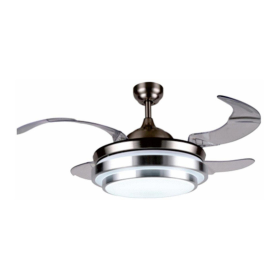
Resumen de contenidos para HOMCOM B31-391
- Página 2 1-Protection class I: The fitting has an earthing connection: The earth wire (yellow /green ) has to be connected to the clip marked with 2-This fitting should only be installed in rooms where direct contact with water is impossible. 3-Consumption in w, according to the speed of the motor. 4-May be operated with a remote control.
-
Página 3: Important Safety Precautions
IMPORTANT SAFETY PRECAUTIONS To ensure the success of installation, Be sure to read instructions and check parts for completeness before starting. Hardware Hardware List Ax2pcs Bx2pcs Cx1pc Dx2pcs Φ6X40 ST4. 8*38 M4*12 SM4*20 NOTE: To reduce the risk of personal injury, only use the mounting kit provided with this ceiling fan. TOOLS REQUIRED Be sure to turn off the power before preparing for installation... - Página 4 PREPARING FOR MOUNTING A x 2PCS B x 2PCS 1. Remove the canopy from the mounting bracket, install the mounting bracket to the ceiling. (please ensure the fixing is able to support minimum moving weight of the fan which is 15.8kg=35Lb) 2.
- Página 5 3. Put the yoke cover and canopy through the down rod, reinsert the nylon ball, pin and screw on the down rod. 4. Lift the fan up and place the nylon ball onto the bracket, Make sure the guide pin of the bracket fits into the slot of the ball.
- Página 6 power supply from ceiling (230V/50Hz) RECEIVER Subtitle: 1: AC IN N (Blue) 2: AC IN L (Brown) 3: Live wire for fan L (Brown) 4: Live wire for Lamp Control LA (Red) 5: Common zero line output N (Blue) MOTOR 6.
- Página 7 7. Install the light kit pan to the motor assembly by tighten the screws. 8. Connect two plugs to connect the LED plate to the entire motor. Place the LED in the center of the panel. 9. Turn the acrylic bowl clockwise until it stops. 10.
-
Página 8: Remote Control
REMOTE CONTROL 1- Fan ON/OF 2- Fast speed 3- Middle speed 4- Low speed 5- 1 Hours delay 6- 2 Hours delay 7- 4 Hours delay 8- Light kit ON/OF Using 1pcs of 12V-23A batteries. IMPORTANTE 1. When the transmitter cannot control the receiver, please check whether the battery switch contact is normal, whether the positive and negative poles are placed correctly, and whether the battery is sufficient. - Página 9 Care and Cleaning WARNING: Make sure the power is off before cleaning your fan. Because of the fan’s natural movement, some connections may become loose. Check the support connections, brackets, and blade attachments twice a year. Make sure they are secure. It is not necessary to remove the fan from the ceiling.
- Página 10 1-Clase de protección I: El accesorio cuenta con una conexión a tierra: El cable de tierra (amarillo / verde) debe ser conectado al clip marcado con señal de 2- Solo coloque o instale el ventilador en una habitación seca, manténgalo alejado de las sustancias húmedas. 3- El consumo es en vatios por la velocidad del motor.
-
Página 11: Precauciones De Seguridad Importantes
PRECAUCIONES DE SEGURIDAD IMPORTANTES Lea todas las instrucciones y verifique si todas las piezas estén presentes antes de empezar la instalación. Hardware Hardware List Ax2pcs Bx2pcs Cx1pc Dx2pcs Φ6X40 ST4. 8*38 M4*12 SM4*20 NOTA: Por motivo de reducir el riesgo de lesiones, utilice el kit proporcionado. HERRAMIENTAS NECESARIAS Apague la energía antes de instalar el ventilador. -
Página 12: Preparación Para La Instalación
PREPARACIÓN PARA LA INSTALACIÓN A x 2PCS B x 2PCS 1. Retire la cubierta de la ménsula de montaje, e instálela en el techo. Asegúrese de que el techo pueda soportar el peso m ínimo del ventilador en movimiento que es de 15,8 kg o 35 libras. 2.Retire la bola de nailon de la varilla inferior, luego saque el pasador y el tornillo del motor. - Página 13 3. Coloque la cubierta del yugo y el dosel a través de la varilla de bajada, vuelva a insertar la bola de nylon, el pasador y el tornillo en la varilla de bajada. 4.Levante el ventilador y coloque la bola de nailon en el soporte. Asegúrese de que el pasador guía del soporte encaje en la ranura de la bola.
- Página 14 Suministro de energía desde el techo (230V/50Hz) RECEPTOR Subtítulo: 1: AC IN N (Azul) 2: AC IN L (Marrón) 3: Cable vivo para el ventilador L (Marrón) 4: Cable vivo para el control de la lámpara LA (Rojo) 5: Salida de línea cero común N (Azul) MOTOR 6.
- Página 15 7. Instale la bandeja del kit de luces en el conjunto del motor apretando los tornillos. 8. Conecte dos enchufes para conectar la placa del LED a todo el motor. 3. Coloque el LED en el centro del panel. 9. Gire la cubeta acrílica en el sentido de las agujas del reloj hasta que se detenga. 10.Vuelva a ensamblar la capota con el soporte y utilice los tornillos de fijación para apretar la capota, asegúrese de que la capota está...
-
Página 16: Control Remoto
CONTROL REMOTO 1- Ventilador ON/OF 2- Velocidad rápida 3- Velocidad media 4- Velocidad baja 5- Retraso de 1 hora 6- 2 Horas de retardo 7- 4 Horas de retardo 8- Kit de luces ON/OF Usando 1pcs de baterías de 12V-23A. IMPORTANTE 1. -
Página 17: Solución De Problemas
Cuidado y limpieza ADVERTENCIA: Asegúrese de que se apaga la energía antes de realizar la limpieza para su ventilador. Dado que el ventilador siempre gira, es posible que algunas conexiones del ventilador podrían aflojarse. Compruebe las conexiones de soporte, la ménsula y los accesorios de las hojas 2 veces cada año. Asegúrese de que estén fijados bien.