Publicidad
Enlaces rápidos
English / Español / Português
Installation, Configuration and
Operation Guide
16898134
Guía de Instalación, Configuración y
Operación
Guia de Instalação, Configuração e
Operação
CFW900 KME/F/G/H-01
M6 x 20 screw
Tornillo M6 x 20
Parafafuso M6 x 20
M6 x 12 screw
Tornillo M6 x 12
Parafafuso M6 x 12
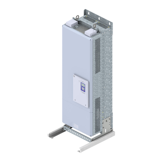
Figure 1.1: Exploded view of the KME/F/G/H-01 kit
Figura 1.1: Montaje desglosado kit KME/F/G/H-01
Figura 1.1: Montagem explodida kit KME/F/G/H-01
1
Figure 1.2: Installation of side brackets
Figura 1.2: Instalación de los soportes laterales
Figura 1.2: Instalação dos suportes laterais
1 - Screw the side brackets into the existing hole in the inverter duct.
1 - Atornillar los soportes laterales en la perforación existente en el
ducto del convertidor.
1 - Parafusar os suportes laterais na furação existente no duto do
inversor.
2
Figure 1.3: Installation of central crossbeams
Figura 1.3: Instalación de los travesaños centrales
Figura 1.3: Instalação das travessas centrais
2 -Screw the central crossbeams between the side brackets.
2 - Atornillar los travesaños centrales entre los soportes laterales.
2 - Parafusar as travessas centrais entre os suportes laterais.
3
Figure 1.4: Fitting of the set on the rails
Figura 1.4: Encaje del conjunto en los rieles
Figura 1.4: Encaixe do conjunto nos trilhos
3 - Fix the rails (see dimension drawing), fit the set and push it up to
the stop.
3 - Fijar los rieles (ver dimensional), encaje el conjunto y empuje hasta
el batiente.
3 - Fixar os trilhos (ver dimensional), encaixe o conjunto e empurre
até o batente.
Publicidad

Resumen de contenidos para WEG CFW900 KME-01
- Página 1 M6 x 20 screw Tornillo M6 x 20 Parafafuso M6 x 20 English / Español / Português M6 x 12 screw Tornillo M6 x 12 Installation, Configuration and Parafafuso M6 x 12 Operation Guide 16898134 Guía de Instalación, Configuración y Operación Guia de Instalação, Configuração e Operação...
- Página 2 KME-01 M8(4X) [14.84] [12.13] [16.18] [31.30] [7.87] [5.12] [30.71] 1146 1095 KMF-01 M10(6X) [15.47] [12.76] [16.81] [45.12] [4.92] [3.74] [43.11] [19.92] [18.70] [0.98] [1.97] [1.97] 1349 1295 KMG-01 M10(6X) [17.83] [15.12] [19.17] [53.11] [5.90] [3.74] [50.98] 1389 1324 KMH-01 M10(8X) [22.28] [19.57] [23.62]...


