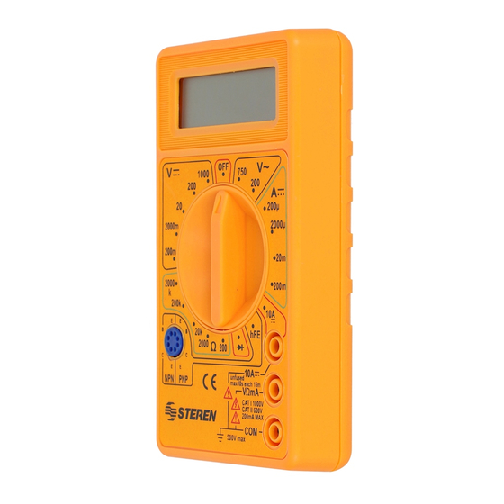
Resumen de contenidos para Steren MUL-010
- Página 1 V0.2 MUL-010 MULTÍMETRO DIGITAL ECONÓMICO 1000 OFF Manual de instrucciones 0915m...
- Página 2 Multímetro digital económico. Por favor, revíselo completamente para estar seguro de cómo utilizar apropiadamente el producto. Para apoyo, compras y todo lo nuevo que tiene Steren, visite nuestro sitio web: www.steren.com La información que se muestra en este manual sirve únicamente como...
-
Página 3: Características
IMPORTANTE • Nunca conecte el multímetro a más de 1000 V de CD o 750 Vrms de CA. • Nunca use un rango inapropiado, ya que podría dañar los circuitos internos del multímetro. • Nunca use el aparato si la cubierta de la batería no está... - Página 4 VOLTÍMETRO DE CD Resistencia de entrada: 1 MΩ para rangos pequeños Capacidad máxima de entrada: 1000 V o pico CA Rango Resolución Precisión (1 año) 18 a 28°C 200 mV 0,1 mV ± (0,5 % de rdg + 2d) 2000 mV 1 mV ±...
-
Página 5: Probador De Diodo Y Transistor
PROBADOR DE DIODO Y TRANSISTOR Rango Condiciones de Precisión prueba lb=10 uA y Transistores NPN y PNP con un Vce=2,8 V rango entre 0-1000 2. INSTRUCCIONES Si al encender el multímetro aparece en la pantalla el mensaje “LOBAT” o “BAT”, deberá reemplazar la batería. -
Página 6: Mediciones De Corriente
Mediciones de corriente en CD y CA 1. Conecte la punta roja a “V mA” y la negra a “COM”. 2. Gire la perilla al rango más alto y redúzcalo gradualmente, dependiendo de la lectura. Esta función está protegida por un fusible de 2 A / 250 V;... -
Página 7: Probador De Diodos
Probador de diodos 1. Conecte la punta roja a “V mA” y la negra a “COM”. La polaridad de la punta roja será positiva. 2. Seleccione la función y realice las mediciones. • Cuando alguna de las puntas no esté conectada (circuito abierto), en la pantalla aparecerá... -
Página 8: Probador De Transistores
Probador de transistores 1. Gire la perilla a la posición hFE. 2. Determine el tipo de transistor que probará y localice el emisor, la base y el colector. El medidor mostrará la ganancia aproximada del transistor entre 0 y 1999. 3. - Página 9 1.- Para hacer efectiva la garantía, presente esta póliza y el producto, en donde fue adquirido o en Electrónica Steren S.A. de C.V. 2.- Electrónica Steren S.A de C.V. se compromete a reparar el producto en caso de estar defectuoso sin ningún cargo al consumidor.
- Página 10 V0.2 MUL-010 DIGITAL MULTIMETER 1000 OFF Manual de instrucciones 0915m...
-
Página 11: Digital Multimeter
DIGITAL MULTIMETER MUL-010 Thank You on purchasing your new Steren product. This manual includes all the feature operations and troubleshooting necessary to install and operate your new Steren´s Digital multimeter. Please review this manual thoroughly to ensure proper installation and operation of this product. - Página 12 IMPORTANT • Do not introduce DC voltages above 1000 VDC or AC voltage above 750 VAC. • Never use an inappropriate range, it would damage the internal circuits. • Never use your multimeter if the protective cover is not properly placed. •...
- Página 13 DC VOLTIMETER Input resistance: 1 MΩ for small ranges Overcharge protection: for peaks higher than 1000 V or peak AC (~). Range Resolution Precision (1 year) 18 to 28°C 200 mV 0.1 mV ± (0.5 % of rdg + 2d) 2000 mV 1 mV ±...
- Página 14 OHMETER Voltaje in an open circuit: - 700 mV Range Resolution Precision 200 ohms 0.1 ohm ± (0.8 % of rdg + 2d) 2000 ohms 1 ohm ± (0.8 % of rdg + 2d) 20 kohms 10 ohm ± (0.8 % of rdg + 2d) 200 kohms 100 ohm ±...
- Página 15 Measuring DC / AC voltage 1. Connect the red testing point to the jack signaled “V Ohms mA” and the black testing point to the jack signaled “COM”. 2. Turn the knob to the VDC / VAC setting and realize the measurement. If you see “1” in the display, it means the measured voltage exceed the selected range.
- Página 16 Measuring DC and AC current 1. Connect the red testing point to the jack signaled “V Ohms mA” and the black testing point to the jack signaled “COM”. 2. Turn the knob to the maximum setting and reduce level by level depending on the reading.
-
Página 17: Measuring Resistances
Measuring resistances 1. Connect the red testing point to “V Ohms mA” and the black testing point to “COM”. 2. Turn the knob on the ohmmeter function. Choose the correct range and take measurements: • When there is an open circuit in the display will show “1”... -
Página 18: Testing Diodes
Testing diodes 1. Connect the red testing point to “V mA” and the black testing point to the jack signaled “COM”. The polarity of the red testing point will be positive. 2. Select the function and realize the measurements. • If one of the testing points is not connected to the circuit, the LCD screen will display “1”, indicating an over range. -
Página 19: Transistor Measurement
Transistor measurement 1. Turn the knob to the hFE setting. 2.Determine the type of the transistor and localize the emitter, base, and collector. The multimeter will show the transistor approximate gain between 0 and 1999. 3. SPECIFICATIONS Maximum common voltage: 500V peak. Operating environment: 0°C to 50°C, less than 80% humidity for 35°, less than 70% humidity from 30 to 50°... - Página 20 Product: Digital Multimeter Part number: MUL-010 Brand: Steren WARRANTY This Steren product is warranted under normal usage against defects in workmanship and materials to the original purchaser for one year from the date of purchase. CONDITIONS 1. This warranty card with all the required information, invoice,...


