Tabla de contenido
Publicidad
Enlaces rápidos
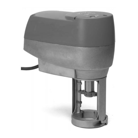
VA7820-GGx-1x / VA7830-GGx-1x
Electric Valve Actuators - Spring Return Model
P/N 14-88375-25 Rev. A
Installation Instructions
Issue Date 06 2009
Figure 1: Dimensions in mm and Mounting Components
Figure 2: Mounting Positions
Figure 3: Manual Override
Johnson Controls, Inc
Building Efficiency
Headquarters: Milwaukee, Wisconsin, USA
Branch Offices: Principal Cities World-wide
®
Johnson Controls
is registered trademark of Johnson Controls, Inc.
www.johnsoncontrols.com
All marks herein are the marks of their respective owners. © 2009 Johnson Controls, Inc.
Publicidad
Tabla de contenido

Manuales relacionados para Johnson Controls VA7820-GG-1 Serie


Resumen de contenidos para Johnson Controls VA7820-GG-1 Serie
- Página 1 Johnson Controls, Inc Building Efficiency Headquarters: Milwaukee, Wisconsin, USA Branch Offices: Principal Cities World-wide ® Johnson Controls is registered trademark of Johnson Controls, Inc. www.johnsoncontrols.com All marks herein are the marks of their respective owners. © 2009 Johnson Controls, Inc.
- Página 2 IS_VA7820-VA7830_P/N 14-88375-25 Rev. A_06 2009 Figure 4: Mounting Actuator on the valve (mod. VA78x0-xxx-11) Figure 5: Mounting Actuator on the valve (mod. VA78x0-xxx-12) This document is subject to change without notice...
- Página 3 IS_VA7820-VA7830_P/N 14-88375-25 Rev. A_06 2009 Figure 6: Wiring diagram VA78x0-GGx-xx Figure 7: Starting Self Calibration Figure 8: Auxiliary Switches setting This document is subject to change without notice...
-
Página 4: General Features
English IS_VA7820-VA7830_P/N 14-88375-25 Rev. A_06 2009 Wiring READ THIS INSTRUCTION SHEET AND THE SAFETY WARNINGS CAREFULLY BEFORE INSTALLING AND SAVE IT FOR FUTURE USE Figure 6: Wiring diagram VA78x0-GGx-1x General Features (a). Wired as Proportional (b). Wired as Floating VA7810-xxx-1x model can be mounted on VG7000T valves: (c). -
Página 5: Technical Specifications
24 VAC models must be powered through a class II 230/24V safety transformer and appropriate fuse. • Do not repair or replace a damaged cable, contact the nearest Johnson Controls commercial system wholesaler. • Do not open the actuator other then aux switches or feedback setting. - Página 6 Français IS_VA7820-VA7830_P/N 14-88375-25 Rev. A_06 2009 Figure 5: Montage de la commande sur la vanne (mod. VA78x0-GGx-12) LISEZ ATTENTIVEMENT LA PRÉSENTE FICHE D’INSTRUCTIONS, AINSI QUE LES AVERTISSEMENTS RELATIFS À LA SÉCURITÉ, AVANT DE PROCÉDER À Vérifier que le coupleur se trouve dans la bonne position. Sinon, le réajuster à l'aide L’INSTALLATION ET CONSERVEZ-LA POUR TOUTE UTILISATION ULTÉRIEURE de la commande manuelle.
-
Página 7: Mode De Fonctionnement Normal
• Ne pas réparer ou remplacer un câble endommagé. Contacter le grossiste • TOUT D’ABORD, régler le signal d’entrée minimum (point de départ) dans la plage systèmes commerciaux Johnson Controls le plus proche. 0...6 VDC (0...12 mA) et confirmer en appuyant sur le bouton d’étalonnage. -
Página 8: Allgemeine Merkmale
Deutsch IS_VA7820-VA7830_P/N 14-88375-25 Rev. A_06 2009 Abbildung 5: Montage des Stellantriebs auf dem Ventil (VA78x0-GGx-12) LESEN SIE DIESE ANLEITUNG UND DIE SICHERHEITSHINWEISE VOR DER INSTALLATION SORGFÄLTIG DURCH, UND BEWAHREN SIE SIE FÜR Stellen Sie sicher, dass sich die Kupplung in der richtigen Stellung befindet. Stellen SPÄTERE REFERENZZWECKE AUF Sie sie andernfalls mittels manueller Betätigung korrekt ein. -
Página 9: Sicherheitshinweise
• Reparieren oder ersetzen Sie beschädigte Kabel nicht, sondern setzen Sie sich mit zurück. Beim Erreichen der dem Eingangssignalwert entsprechenden Stellung dem nächsten Großhändler von Johnson Controls in Verbindung. leuchtet die LED dauerhaft grün. • Öffnen Sie den Stellantrieb ausschließlich zur Einstellung der Hilfsschalter oder des •... - Página 10 Italiano IS_VA7820-VA7830_P/N 14-88375-25 Rev. A_06 2009 Figura 5: Montaggio dell'attuatore sulla valvola (mod. VA78x0-GGx-12) LEGGERE ATTENTAMENTE QUESTE ISTRUZIONI E LE AVVERTENZE SULLA SICUREZZA PRIMA DELL'INSTALLAZIONE E CONSERVARLE PER USO Assicurarsi che il giunto si trovi nella posizione corretta; in caso contrario, FUTURO riposizionarlo mediante la regolazione manuale.
-
Página 11: Specifiche Tecniche
• In caso di cavo danneggiato non riparare o sostituire ma rivolgersi al più vicino necessario reimmettere i valori. rivenditore Johnson Controls. • Impostare il segnale di ingresso massimo entro l'intervallo 3…10 VDC (6…20 mA) • Aprire il coperchio del'attuatore solo per l'impostazione degli interruttori ausiliari o e confermarlo premendo il pulsante di calibrazione. -
Página 12: Montaje
Español IS_VA7820-VA7830_P/N 14-88375-25 Rev. A_06 2009 Figura 5: Montaje del actuador en la válvula (mod. VA78x0-GGx-12) ANTES DE LA INSTALACIÓN, LEA DETENIDAMENTE ESTAS INSTRUCCIONES Y LAS ADVERTENCIAS DE SEGURIDAD, Y CONSÉRVELAS PARA Asegúrese de que el acoplador esté en la posición correcta. Si no fuese así, CONSULTARLAS EN EL FUTURO reajústelo mediante el procedimiento de supresión manual. -
Página 13: Modo De Funcionamiento Normal
• No intente reparar ni sustituir cables dañados. Consulte al distribuidor comercial de • Una vez concluido el procedimiento, el actuador volverá a su modo de Johnson Controls más próximo. funcionamiento, alcanzando la posición correspondiente al valor de la señal de •... - Página 14 Nederlands IS_VA7820-VA7830_P/N 14-88375-25 Rev. A_06 2009 Figuur 5: Bekrachtiger op het ventiel monteren (mod. VA78x0-GGx-12) LEES DIT INSTRUCTIEBLAD EN DE VEILIGHEIDSWAARSCHUWINGEN ZORGVULDIG VOORDAT DE INSTALLATIE WORDT UITGEVOERD, EN Zorg ervoor dat het koppelstuk in de juiste positie staat. Als dit niet het geval is, moet BEWAAR DIT MATERIAAL ZODAT U HET IN DE TOEKOMST OOK NOG KUNT u dit wijzigen door middel van handmatige wijziging.
- Página 15 Nederlands IS_VA7820-VA7830_P/N 14-88375-25 Rev. A_06 2009 Aangepast ingangssignaal • Alle bedrading moet voldoen aan plaatselijke voorschriften en mag uitsluitend worden uitgevoerd door geautoriseerd personeel. Houd hoog- en DIP SWITCH 3 = ON – Max. bereik 0-10 VDC of 0-20 mA laagspanningsbedrading gescheiden.
- Página 16 Svenska IS_VA7820-VA7830_P/N 14-88375-25 Rev. A_06 2009 Kabeldragning LÄS DET HÄR INSTRUKTIONSBLADET OCH SÄKERHETSANVISNINGARNA NOGGRANT INNAN DU INSTALLERAR MODULEN OCH SPARA DEM FÖR Figur 6: Kopplingsschema VA78x0-GGx-1x FRAMTIDA BRUK (a). Proportionell reglering Allmänna funktioner (b). Inkrementell reglering (c). ON-OFF-reglering Modellen VA7810-xxx-1x kan monteras på VG7000T-ventiler: (d).
-
Página 17: Ställdonets Tillstånd
24 VAC-apparater måste försörjas genom en säkerhetstransformator av klass II 230/24 V och lämplig säkring. • Om kabeln är skadad ska du inte reparera eller byta ut den. Kontakta i stället närmaste Johnson Controls-återförsäljare. • Ställdonet får endast öppnas i samband med inställning av hjälpkontakter eller återföring. - Página 18 Česky IS_VA7820-VA7830_P/N 14-88375-25 Rev. A_06 2009 Zapojení PŘED INSTALACÍ SI POZORNĚ PŘEČTĚTE TYTO POKYNY A BEZPEČNOSTNÍ VAROVÁNÍ A USCHOVEJTE JE PRO POZDĚJŠÍ POUŽITÍ Obrázek 6: Schéma zapojení modelu VA78x0-GGx-1x (a) Zapojení proporcionálního řízení Všeobecné funkce (b) Pohyblivé zapojení Model VA7810-xxx-1x je možné připevnit na ventily VG7000T: (c) Zapojení...
-
Página 19: Technické Údaje
Modely využívající 24V střídavý proud je třeba napájet pomocí bezpečnostního měniče 230/24 V třídy II s vhodnou pojistkou. • Poškozenou kabeláž neopravujte ani nevyměňujte. Místo toho se obra″te na nejbližší velkoobchod komerčních systémů Johnson Controls. • Spouštěč neotvírejte jinak, než v rámci používání pomocných spínačů a nastavení zpětné vazby. - Página 20 Polski IS_VA7820-VA7830_P/N 14-88375-25 Rev. A_06 2009 Rysunek 5: Montaż siłownika na zaworze (model VA78x0-GGx-12) PRZED INSTALACJĄ NALEŻY UWAŻNIE PRZECZYTAĆ TĘ INSTRUKCJĘ I OSTRZEŻENIA DOTYCZĄCE BEZPIECZEŃSTWA ORAZ ZACHOWAĆ JE W Należy upewnić się, że łącznik znajduje się w prawidłowym położeniu. W przeciwnym CELU PÓZNIEJSZEGO UŻYCIA wypadku należy wyregulować...
-
Página 21: Procedura Kontroli
0...6 VDC (0...12 mA) i zatwierdzić go, naciskając przycisk kalibracji. Johnson Controls. • Dioda LED zaświeci na zielono przez 2 sekundy, wskazując prawidłowe ustawienie. • Nie należy otwierać siłownika w celu innym niż ustawienie przełączników Jeśli dioda LED zaświeci na żółto przez 2 sekundy, oznacza to, że ustawienie jest...