Tabla de contenido
Publicidad
Idiomas disponibles
Idiomas disponibles
Enlaces rápidos
No: 23992 – 06/20 rev. 6
Catalog Numbers • Les Numéros de Catalogue • Números de Catálogo: LMRC-211/LMRC-211-347
Country of Origin: Made in China • Pays d'origine: Fabriqué en Chine • País de origen: Hecho en China
LMRC-211-U and LMRC-211-347 -U are BAA and TAA compliant (Product produced in the U.S.)
This unit is pre-set for Plug n' Go™ operation, adjustment
is optional.
For full operational details, adjustment and more features of the
product, see the DLM System Installation Guide provided with
Wattstopper room controllers, and also available at
www.legrand.us/Wattstopper.
Installation shall be in accordance with all applicable
regulations, local and NEC codes. Wire connections shall
be rated suitable for the wire size (lead and building wiring)
employed.
For Class 2 DLM devices and device wiring: To be connected
to a Class 2 power source only. Do not reclassify and install as
Class 1, or Power and Lighting Wiring.
IMPORTANT SAFEGUARDS
When using electrical equipment, basic safety precautions
should always be followed including the following:
a. READ AND FOLLOW ALL SAFETY INSTRUCTIONS.
b. Do not use outdoors.
c. Do not mount near gas or electric heaters.
d. Equipment should be mounted in locations and
at heights where it will not readily be subjected to
tampering by unauthorized personnel.
e. The use of accessory equipment not recommended by
the manufacturer may cause an unsafe condition.
f. Do not use this equipment for other than intended use.
g. Installation should be performed by qualified service
personnel.
SAVE THESE INSTRUCTIONS
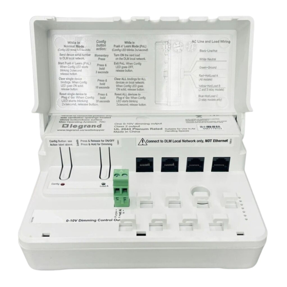
CAUTION: TO CONNECT A COMPUTER TO THE DLM LOCAL NETWORK USE
THE LMCI-100. NEVER CONNECT THE DLM LOCAL NETWORK TO AN
ETHERNET PORT – IT MAY DAMAGE COMPUTERS AND OTHER CONNECTED
Wattstopper
DLM Single Relay w/0-10V Dimming Room Controller
DLM relais simple avec contrôleur de pièce de gradation 0-10 V
Relé simple DLM con controlador de regulación de habitación de 0 a 10 V
Quick Start Guide • Guide de démarrage rapide • Guía de inicio rápido
SPECIFICATIONS
Voltage
LMRC-211 Input Voltage ... Single Phase 120/230/240/277VAC, 50/60Hz
LMRC-211-347 Input Voltage ................................. 347VAC, 50/60Hz
Load Requirements
LMRC-211 relay rated for up to:
Incandescent. .........................................................20A @ 120VAC
Ballast .............................................................20A @ 120/277VAC
E-Ballast ............................................................16A@120/277VAC
Motor ..................................................................... 1Hp @ 120VAC
LMRC-211-347 relay rated for up to:
Ballast/LED Driver ..................................................15A @ 347VAC
Class 2 Dimming Output, 0-10V ......................sinks up to 100mA per channel
Output to DLM Local Network ............................... up to 250mA @ 24VDC
Connection to the DLM Local Network .................................. 4 RJ-45 ports
DLM Local Network characteristics when using LMRC-11x/2xx room
controllers:
Low voltage power provided over Cat 5e cable (LMRJ);
max current 800mA. Supports up to 64 load addresses,
48 communicating devices including up to 4 LMRC-10x
series and/or LMPL-101 controllers, and LMPB-100.
Free topology up to 1,000' max.
Environment ............................................................... For Indoor Use Only
Operating Temperature ...............................32° to 158°F (0° to 70°C)
Storage Temperature .................................23° to 176°F (-5° to 80°C)
Relative Humidity .....................................5 to 95% (non condensing)
Patent Pending
UL2043 Plenum Approved – Suitable for Use in Air Handling Spaces
UL/CUL Listed under UL60730:
Type 1
Operating Control – For Electronic Ballast, CFLs, LED, LED Lamps,
Motors and Incandescent Lamps.
Independently Mounted for Surface Mounting
Pollution Degree 2
Software Class A
Impulse Voltage Rated – 4000V
The LMRC-211 is also Complementary Listed to "Emergency
Lighting Equipment", (UL924) intended for Indoor Dry Locations
(does not apply to LMRC-211-347).
EQUIPMENT.
®
Publicidad
Tabla de contenido

Manuales relacionados para LEGRAND Wattstopper LMRC-211


Resumen de contenidos para LEGRAND Wattstopper LMRC-211
- Página 1 DLM System Installation Guide provided with Low voltage power provided over Cat 5e cable (LMRJ); Wattstopper room controllers, and also available at www.legrand.us/Wattstopper. max current 800mA. Supports up to 64 load addresses, 48 communicating devices including up to 4 LMRC-10x Installation shall be in accordance with all applicable series and/or LMPL-101 controllers, and LMPB-100.
-
Página 2: Mounting The Controller
MOUNTING THE CONTROLLER The room controller mounts as the cover for a four square deep junction box. After connecting the load and line wires, secure the LMRC-211 to the WARNING: TURN THE POWER OFF AT cover tabs on a deep junction box using two screws. THE CIRCUIT BREAKER BEFORE WIRING. - Página 3 USING THE LMRC-211 WITH EMERGENCY LIGHTING NOTE: If any Emergency Circuits are fed or controlled from a panel, it must be located electrically where fed from a UPS, generator, or other guaranteed source of power during emergency and power outage situations. When used with an ELCU Violet Emergency...
- Página 4 UNIT ADJUSTMENT - PUSH N’ LEARN (PNL) Load Selection Procedure. A configuration button (Config) allows access to our patented Push n’ Learn™ technology to change binding relationships between sensors, switches and loads. Step 1 Enter Push n’ Learn. Config button & red LED Press and hold the Config button (on any DLM device) for 3 seconds.
-
Página 5: Sauvegardes Importantes
LMRC-211-347 Tension d’entrée ......... 347VCA, 50/60Hz du système DLM fourni avec Wattstopper contrôleurs de pièce et aussi Exigences pour la charge disponible au www.legrand.us/Wattstopper. LMRC-211 Relais a une capacité de: Incandescence...............20A à 120VCA L'installation doit être effectuée conformément à tous les Ballast ..............20A à... - Página 6 MONTAGE LE CONTRÔLEUR Le contrôleur s’installe à la place du couvercle d’une boîte de jonction profonde carré. Après avoir raccordé les câbles de charge et tension, sécuriser le LMRC-211 dans les trous du couvercle de la boîte de jonction avec les deux vis. ATTENTION: Montez l’appareil en position verticale ou horizontale verticale avec les ouvertures de ventilation latérales situées au- dessus de la surface inférieure / de la base.
- Página 7 UTILISATION DU LMRC-211 AVEC UN ÉCLAIRAGE D’URGENCE REMARQUE: Si des circuits d’urgence sont alimentés ou contrôlés à partir d’un panneau, ils doivent être situés électriquement où ils sont alimentés par un UPS, un générateur ou toute autre source d’alimentation garantie pendant les situations d’urgence et de panne de courant.
- Página 8 RÉGLAGE DE L’APPAREIL OPTIONNEL - PUSH N’ LEARN (PNL) Procédure de sélection de la charge Un bouton de configuration (config) permet d’accéder à notre technologie brevetée Push n’ LearnMC pour modifier les liens entre les détecteurs, les interrupteurs et les charges. Étape 1 Entrer en mode Push n’...
-
Página 9: Salvaguardias Importantes
LMRC-211-347 Voltaje de entrada .........347VCA, 50/60Hz proporciona con Wattstopper controladores de habitación; también Requerimientos de carga está disponible en www.legrand.us/Wattstopper. LMRC-211 ..........No debe exceder 20 A en total Cada relé está calificado para hasta: La instalación debe realizarse conforme con todas las Incandescente. -
Página 10: Conectividad
CONECTIVIDAD El dispositivo LMRC-211 se comunica con todos los demás dispositivos DLM conectados a la red local DLM. Los esquemas de conexiones que se muestran son únicamente a modo de ejemplo. Los cables LMRJ de bajo voltaje se pueden conectar a cualquier dispositivo DLM con un receptáculo RJ45 abierto. -
Página 11: Montaje Del Controlador
MONTAJE DEL CONTROLADOR El controlador sirve como la cubierta de la caja de conexiones electricas. ADVERTENCIA: DESCONECTE LA Después de conectar los cables, asegure el controlador a las lengüetas de ALIMENTACIÓN EN EL DISYUNTOR la caja de conexión con dos tornillos. ANTES DEL CABLEADO. -
Página 12: Solución De Problemas
No. 23992 – 06/20 rev. 6 © Copyright 2020 Legrand All Rights Reserved. 800.879.8585 © Copyright 2020 Tous droits réservés Legrand. www.legrand.us/wattstopper © Copyright 2020 Legrand Todos los derechos reservados.