Tabla de contenido
Publicidad
Idiomas disponibles
Idiomas disponibles
Enlaces rápidos
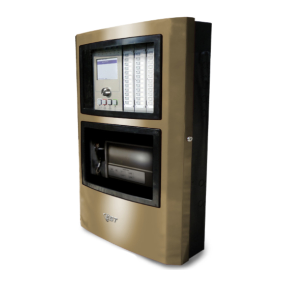
EST3X Fire Alarm Control Panel Installation Sheet
EN ES FR PT
EN: Installation Sheet
Description
This document shows you how to install the components
received with your EST3X Fire Alarm Control Panel, and how
to power up the system. Please read the installation and
power-up procedures in their entirety before proceeding.
Installation
Install the components in the order shown in this document.
Refer to Figure 1 for an exploded view of the order.
Caution:
Circuit boards are sensitive to electrostatic discharge
(ESD). To avoid damage, follow ESD handling procedures.
Notes
•
Make sure the installation location is free from
construction dust and debris, and is not subject to extreme
temperature ranges and excess humidity.
•
Ensure sufficient floor and wall space to avoid obstructions
during installation and servicing.
•
When installing the cabinet, use fasteners that can support
the full weight of the cabinet, including standby batteries.
Be sure to tighten the fasteners firmly to prevent the
cabinet from vibrating.
© 2011 UTC Fire & Security. All rights reserved.
•
Remove a panel component from its protective antistatic
packaging only for inspection or installation.
•
Do not install standby batteries at this time.
•
Install separately ordered option cards or modules on the
SFS1-CPU or backbox before installing the SFS1-ELEC.
To install the EST3X:
1.
Unpack the equipment and make sure it is not damaged.
Be sure to remove the installation sheets from component
accessory bags.
2.
Install the backbox. Follow the instructions on the CAB6B
Backbox Installation Sheet (3101764-ML).
3.
Install the power supply. Follow the instructions on the
PS10-4B Power Supply Board Installation Sheet
(P/N 3101774-ML).
4.
Install the chassis electronics assembly. Follow the
instructions on the SFS1-ELEC Chassis Electronics
Assembly Installation Sheet (P/N 3101766-ML).
5.
Install the door. Follow the instructions on the
4X-CAB6D(R) Door Installation Sheet (P/N 3101765-ML).
Control panel power-up
WARNING:
Electrocution hazard. To avoid personal injury or
death, make sure the distribution circuit providing mains AC is
rendered inoperative prior to connecting mains input wiring to
the PS10-4B Power Supply.
To power up the control panel:
1.
Connect mains AC (primary power) to the power supply as
shown in the "Mains input wiring" figure on the PS10-4B
Power Supply Board Installation Sheet.
2.
Apply power to the panel.
The Power LED illuminates and the LCD screen turns on.
Depending on your setup, events may display prior to
configuration.
3.
Press the Acknowledge and Panel Silence buttons on the
user interface to acknowledge any events and silence the
panel.
This completes the control panel power-up procedure.
1 / 8
P/N 3101887-ML • REV 2.0 • ISS 06DEC11
Publicidad
Tabla de contenido

Resumen de contenidos para UTC Fire & Security EST3X
- Página 1 This document shows you how to install the components 4X-CAB6D(R) Door Installation Sheet (P/N 3101765-ML). received with your EST3X Fire Alarm Control Panel, and how to power up the system. Please read the installation and power-up procedures in their entirety before proceeding.
-
Página 2: Regulatory Information
Figure 1: EST3X cabinet exploded view of installation order (1) CAB6 Backbox (4) PS10-4B protective cage for ULC applications only 4X-CAB6D(R) Door (2) PS10-4B insulator plate (5) SFS1-ELEC Chassis Electronics Assembly (3) PS10-4B power supply board Specifications Regulatory information CAB6B... -
Página 3: Instalación
Fuente componentes recibidos con su Panel de Control de Alarmas de Alimentación de PS10-4B. Anti Incendio EST3X, y cómo encender el sistema. Por favor, lea completamente los procedimientos de instalación y encendido antes de continuar. -
Página 4: Información De Contacto
Clase ambiental UL: Ambientes interiores secos Figura 1: Vista detallada del orden de instalación de EST3X (1) Caja de conexiones de CAB6 (2) Placa aislante de PS10-4B (3) Tarjeta de alimentación de PS10-4B (4) Caja protectora de PS10-4B únicamente para aplicaciones ULC... -
Página 5: Caractéristiques Techniques
Ce document vous explique comment installer les composants reçus avec le panneau de commande de l’alarme-incendie EST3X et comment mettre le système sous tension. Veuillez Mise sous tension du panneau de lire les procédures d’installation et de mise sous tension commande intégralement avant de poursuivre. - Página 6 Classe de service UL : milieu intérieur sec Figure 1 : Vue éclatée de l’ordre d’installation de l’armoire EST3X (1) Boîtier arrière CAB6 (2) Plaque isolante PS10-4B (3) Carte d’alimentation PS10-4B (4) Dispositif de protection du bloc d’alimentation PS10-4B pour les applications ULC uniquement...
-
Página 7: Especificações
Esse documento mostra como instalar os componentes recebidos com seu Painel de Controle de Alarme de Incêndio EST3X, e como ativar o sistema. Por favor, leia os Para ligar o painel de controle: procedimentos de instalação e ativação em sua totalidade Conecte a fiação AC (força primária) à... - Página 8 Informação de contato Para informação de contato, veja www.utcfireandsecurity.com. Figura 1: Gabinete EST3X - esquema da ordem de instalação (1) Caixa CAB6 (2) Placa isolante PS10-4B (3) Cartão fonte de alimentação PS10-4B (4) Gaiola protetora PS10-4B apenas para aplicações ULC (5) Conjunto do Chassi Eletrônico SFS1-ELEC...
