Tabla de contenido
Publicidad
Idiomas disponibles
Idiomas disponibles
Enlaces rápidos
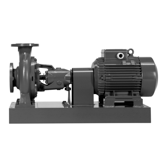
Pompe centrifughe orizzontali ad aspirazione assiale PN 10 con sopporto
Secondo norma europea EN 733
Horizontal end-suction centrifugal pumps PN 10 with bearing bracket
In accordance with european standard EN 733
Horizontale Kreiselpumpen mit axialem Eintritt PN 10 mit Lagerträger
Nach europäischer Norm EN 733
Pompes centrifuges horizontales à aspiration axiale PN 10 avec palier
Selon la norme européenne EN 733
Bombas centrifugas horizontales con aspiración axial PN 10 y soporte
Según norma europea EN 733
Horisontal axial-sugs centrifugalpumpar PN 10 med lagerbock
Enligt Europastandard EN 733
N, N4
ISTRUZIONI ORIGINALI PER L'USO
ORIGINAL OPERATING INSTRUCTIONS
ORIGINAL BETRIEBSANLEITUNG
INSTRUCTIONS ORIGINALES POUR L'UTILISATION
INSTRUCCIONES ORIGINALES DE USO
ORIGINAL DRIFT/INSTALLATIONSANVISNINGAR
PN10
EN 733
Pagina
4
Page
9
Seite
14
Page
19
Página
24
Sidan
29
.
34
Italiano
English
Deutsch
Français
Español
Svenska
Publicidad
Tabla de contenido

Manuales relacionados para Calpeda N Serie


Resumen de contenidos para Calpeda N Serie
- Página 1 Pompe centrifughe orizzontali ad aspirazione assiale PN 10 con sopporto Secondo norma europea EN 733 Horizontal end-suction centrifugal pumps PN 10 with bearing bracket In accordance with european standard EN 733 Horizontale Kreiselpumpen mit axialem Eintritt PN 10 mit Lagerträger Nach europäischer Norm EN 733 Pompes centrifuges horizontales à...
-
Página 2: Tabla De Contenido
Indice Inhaltsverzeichnis Italiano Deutsch Argomento Pagina Gegenstand Seite Condizioni d’impiego Anwendungsbereich Installazione Aufstellung 2.1. Fondazione 2.1. Fundamentgestaltung Tubazioni Rohrleitungen 3.1 Collegamento delle tubazioni 3.1 Rohrleitungen-Anschluß Allineamento del gruppo pompa-motore Ausrichtung des Pumpen-Motor-Aggregats 4.3 Sostegno aggiunto del sopporto 4.3 Zusätzliche Unterstützung des Lagerträgers 16 Collegamento elettrico Elektrischer Anschluß... - Página 3 Índice Español Sumario Página Condiciones de empleo Instalación 2.1. Cimentación 2.1. Instalación de tubos 3.1 Conexión de las tuberías Alineación del grupo Bomba - Motor 4.3 Apoyo añadido al soporte Conexiónado eléctrico Puesta en marcha 6.1 Parada Control y mantenimiento 7.1 Bombas con cierre mecánico 7.2 Bombas con cierre prensa estopa 7.3 Rodamientos de bolas y lubricación...
- Página 4 Pompe centrifughe re protetto dalle intemperie e dall’esposizione al sole. Evitare che vi siano ostacoli per la ventila- orizzontali ad aspirazione zione del motore e prevedere che siano possibili ispezioni e manutenzioni durante il funzionamento. assiale PN 10 con sopporto 2.1.
-
Página 5: Collegamento Delle Tubazioni
3. Tubazioni 3.1. Collegamento delle tubazioni Non usare la pompa come sostegno delle Prevedere il diametro in modo che la velocità del tubazioni. Le tubazioni devono essere ancorate liquido non superi 1,5 m/s nell’aspirazione ed i su propri appoggi (fig. 4). 3 m/s nella mandata. -
Página 6: Sostegno Aggiunto Del Sopporto
Lifting the pump-motor unit Con comparatore o riga controllare l’allineamento - Serraggio alla coppia prevista delle viti laterali (coassialità) della fascia esterna dei semigiunti. del secondo semiguscio. I controlli vanno eseguiti su 4 punti equidistanti - Ripetere la sequenza per l’ultima coppia di viti. sulla periferia e diametralmente opposti (fig. -
Página 7: Collegamento Elettrico
Dopo l’allineamento, prima dell’avvia- Avviare la pompa con la saracinesca in man- mento applicare la protezione giunto data chiusa. Aprire poi lentamente la saracine- (protezione anti infortunistica contro il sca in mandata regolando il punto di funziona- mento, entro i limiti indicati in targa. contatto). - Página 8 La guarnizione a treccia deve essere sostituita Prima di rimettere in marcia il gruppo controllare quando le sue proprietà di tenuta sono sensibil- che l’albero non sia bloccato da incrostazioni o mente diminuite. altre cause e riempire completamente di liquido il Un pacco troppo compresso, indurito e secco cau- corpo pompa.
-
Página 9: Operating Conditions
Make sure motor ventilation is not impeded and Horizontal end-suction provide access around the unit for inspection and centrifugal pumps PN 10 maintenance during operation. with bearing bracket 2.1. Foundation The smaller units are mounted on a single-piece, In accordance with european standard EN 733 channel-steel baseplate with a high degree of torsional strength. -
Página 10: Pipe-Work
3. Pipe-work 3.1. Connecting the pipe-work Do not use the pump to support pipes. Pipes The inside diameter of pipes depends on the deli- must be anchored on their own supports (fig. 4). very required. The diameter should be determined so that the Pipes must be modified if they do not correspond liquid flow velocity will not exceed 1.5 m/sec in the exactly with th eposition of connections to avoid... -
Página 11: Extra Support For Bearing Housing
Sollevamento gruppo pompa-motore Lifting the pump-motor unit Control procedure must be performed at 4 diametri- - Insert the two lateral screws of the first half-cou- cally opposed, equidistant points on the periphery pling. (fig. 6A). - Insert and tighten the two lateral screws of the second half-coupling at the required torque. -
Página 12: 5, Electrical Connection
between pump casing feet and baseplate. valve slowly and completely, keeping the delivery First tighten the screws joining the foot and the gate valve open to release the air. base and then, the screw between the foot and the Close the delivery gate valve completely, and check support. -
Página 13: Pumps With Stuffing Box
7.2. Pumps with stuffing box Before re-starting the unit, make sure the shaft is not jammed by incrustation or deposits and com- On starting for the first time, slightly loosen the pletely refill the pump casing with liquid. stuffing box gland so that seal is decompressed. Then adjust the stuffing box gland to obtain a nor- Disconnect electrical power before any mal degree of dripping which will indicate that the... -
Página 14: Anwendungsbereich
Horizontale Kreiselpumpen Normalerweise muß das Pumpen-Motor-Aggregat vor Witterungseinflüssen und Sonneneinstrahlung mit axialem Eintritt PN 10 geschützt werden. Auf eine unbehinderte Motor- ventilation achten und ausreichend Raum für In- mit Lagerträger spektionen und Wartungsarbeiten während des laufenden Betriebs vorsehen. Nach europäischer Norm EN 733 2.1. -
Página 15: Rohrleitungen-Anschluß
3. Rohrleitungen 3.1. Rohrleitungen-Anschluß Die Pumpe darf nicht als Stützpunkt für die Lei- Der Innendurchmesser der Leitungen hängt von tungen verwendet werden. Die Leitungen müssen dem gewünschten Förderstrom ab. Der Durch- auf eigenen Stützen verankert sein (s. Abb. 4). Die messer soll so bemessen sein, daß... -
Página 16: Zusätzliche Unterstützung Des Lagerträgers
Sollevamento gruppo pompa-motore Lifting the pump-motor unit Mit Taster oder Lineal ist die Ausrichtung (Koaxia- ersten Kupplungshälfte mit vorgesehenen lität) der Außenseite der Kupplungshälften zu kon- Drehmoment fest. trollieren. Führen Sie die zwei seitlichen Schrauben der Die Kontrolle wird auf 4 Punkten ausgeführt, die ersten Kupplungshälfte ein. -
Página 17: Elektrischer Anschluß
Bei Ausrichtungsarbeiten werden vor Leitungsan- Wenn der Wasserspiegel auf der Saugseite oberhalb der Pumpe ist (Zulaufbetrieb) schluß die Schrauben des Stützfußes gelöst, um Spannungen oder Verschiebungen der Achsenhö- Absperrschieber in der Zulaufleitung langsam und vollständig öffnen, um die Pumpe zu füllen. Dabei he zu vermeiden. -
Página 18: Pumpen Mit Stopfbuchspackung
Es sind Vorsichtsmaßnahmen einzuleiten, damit die Vor Neustart wird kontrolliert, daß die Welle nicht Dichtungsoberflächen nicht durch Schläge oder durch Verunreinigungen, Rost oder andere Ursa- Stöße beschädigt werden. chen blockiert ist. Das Pumpengehäuse wird voll- ständig mit Flüssigkeit aufgefüllt. 7.2. Pumpen mit Stopfbuchspackung Bei der Inbetriebnahme wird die Stopfbuchsbrille Alle Arbeiten am Aggregat nur bei abge- leicht gelöst, damit die Dichtung dekomprimiert wird. -
Página 19: Conditions D'uTilisation
Pompes centrifuges En principe, le groupe pompe-moteur doit être pro- tégé contre les intempéries et ne doit pas être direc- horizontales à aspiration tement exposé aux rayons du soleil. Eviter tout ob- stacle s'opposant à la ventilation du moteur et laisser axiale PN 10 avec palier autour un espace suffisant pour permettre l'entretien et le contrôle du groupe lors du fonctionnement. -
Página 20: Tuyauteries
3. Tuyauteries 3.1. Raccordement des tuyauteries Ne jamais utiliser la pompe comme point d'an- Prévoir des tuyaux d'un diamètre tel que le débit crage des tuyaux. Les tuyaux doivent être sup- n'excède pas 1,5 m/s à l'aspiration et 3 m/s au portés de façon appropriée (voir fig. - Página 21 plements (coaxialité). Visser les vis au serrage préconisé par le fabri- Effectuer le contrôle sur 4 points équidistants et cant sur la notice d’instruction de l’accouplement. diamétralement opposés de la périphérie (voir fig. 6A). Contrôler que le rotor tourne facilement à la main. L’alignement doit être vérifié...
-
Página 22: Branchement Électrique
Une fois le lignage terminé, remettre en ment fermée. Ouvrir ensuite, progressivement, la place la protection de l'accouplement vanne de refoulement et régler le point de fonc- avant de démarrer la pompe (mesure de tionnement de la pompe en respectant les limites sécurité... -
Página 23: Roulements À Billes Et Lubrification
La garniture doit être remplacée dès que ses proprié- Avant de remettre en service le groupe, remplir tés d'étanchéité se sont considérablement réduites. complètement de liquide le corps de pompe et Une garniture trop comprimée durcit ou sèche entraî- s'assurer que l'arbre n'est pas bloqué (par suite nant l'usure anormale du manchon d'arbre. -
Página 24: Condiciones De Empleo
exposición del sol. Bombas centrifugas También habrá que evitar obstáculos que perjudi- horizontales con aspiración quen la correcta ventilación del motor, así como prever que sea posible la inspección y el manteni- axial PN 10 con soporte miento durante el funcionamiento del grupo. 2.1. -
Página 25: Instalación De Tubos
3. Instalación de tubos 3.1. Unión de los tubos No usar la bomba como soporte de las tube- Prever el diámetro de manera que la velocidad rías. Los tubos tienen que ser anclados sobre sus del liquido no supere 1,5m/s en la aspiración, propios apoyos. -
Página 26: Grupo Bomba-Motor Con Acoplamiento Rex-Viva
pompa-motore Lifting the pump-motor unit Con comparador o regla controlar el alineamiento - apretar al par previsto los tornillos laterales del coaxial de las caras externas de los semi acopla- segundo aro. mientos. - repetir la secuencia para los últimos dos tornillos. Los controles vienen realizados en 4 puntos equi- Efectuar el apriete de los tornillos al par previsto distantes sobre la periferia y diametralmente... -
Página 27: Conexiónado Eléctrico
Después del alineamiento, y antes de Abrir lentamente la compuerta de la impulsión la puesta en marcha, colocar la pro- regulando el punto de funcionamiento, dentro de tección del acoplamiento. los limites indicados en la placa de características. (Protección contra accidentes). No hacer funcionar la bomba más 5. -
Página 28: Rodamientos De Bolas Y Lubricación 28 7
La estopada debe ser sustituida cuando sus pro- Antes de poner nuevamente en marcha el grupo, piedades de estanquidad son afectadas. controlar que el eje no esté bloqueado por incru- Una estopada demasiado comprimida, endureci- staciones u otras causas, y rellenar completa- da, o seca, es motivo del desgaste de la camisa mente de líquido el cuerpo de la bomba. -
Página 29: Förutsättningar
Uppställningsplatsen skall vara skyddad mot vat- Horisontal axial-sugs tenspolning, regn, snö etc. centrifulgalpumpar PN 10 Pumpen skall vara åtkomlig för tillsyn och skötsel samt god ventilation för motorns kylluft. med lagerbock Enligt Europastandard EN 733 N, N4 2.1. Fundament De mindre pumparna är monterad på en bockad stålplatta med en hög vridstyvhet. -
Página 30: Rörledningar
3. Rörledningar 3.1. Anslutning av rörledningar Använd ej pumpen som stöd för rörledningar- Rörens inre diameter beror på den vätskemängd na. Rörledningarna måste förankras så att som skall pumpas och väljes så att vätskehasti- pumphuset ej belastas med dess tyngd samt gheten ej överstiger 1,5 m/sek i sugledningen uppriktas så... -
Página 31: Extra Stöd För Lagerbocken
omkretsen och skillnaden får vara högst 0,1 mm. kopplingshalvan med erforderligt moment. Med en riktlinjal kontrolleras halvornas koncentri- - Repetera proceduren för de andra skruvarna.. tet. Även detta skall ske på fyra diametrala ställen Momenten för åtdragning finns i kopplingstill- 4.93.036 och avvikelsen får vara högst 0,1 mm (bild 6A). -
Página 32: Elanslutning
Efter uppriktningen före uppstart av Starta pumpen med stängd ventil på trycksi- pumpen monteras kopplingsskyddet. dan. Öppna sedan sakta ventilen på trycksidan tills (Skyddsåtgärd för att ej komma i kontakt önskad volymström erhålles. med kopplingen). Elmotorn kan bli överbelastad om volymströmmen överstiger den på... -
Página 33: Kullager Och Smörjning
Observera att det alltid skall droppa något från Före återstart, vrid runt axeln för hand samt fyll boxen annars bränner packningarna och axeln pumpen och sugledningen helt med vätska. eller axelfodret skadas. Se alltid till att elströmmen är från- Om packboxen blivit för hårt dragen så att smörj- kopplad vid service av pumpen. - Página 34 PN10 EN 733 N, N4 4.93.038/1 . 2). : 90°C. : 10 : 40 °C. N= 2900 N4= 1450 4.93.038 N (2900 ,,,,, 2,2 7,5 30 75 N4 (1450 ,,,,, 7,5 30 75 ( ), . 70 80 85 90 60 40 20 10 N, N4 ( EN 733)
- Página 35 . 4). (DN) (Q). 50 65 80 100 125 150 200 250 300 . / 10,5 19 28,6 45 75 108 215 350 508 PN10 PN16 . 4). 2-2,5 . 5). 4.93.040 4.1. "N-EUPEX" (3-4...
- Página 36 . 6A). 4.93.036 . 6A 2.1, 3.1, 4.1). 4.2. "Rex- Viva" . 6 ). PER VITI M12 riga straight edge P057/1 . 6B EN733 112÷180 180÷250 280÷315 FÜR SCHRAUBEN M12...
- Página 37 ≥ 5,5 “ ” . 8), 4.93.141...
- Página 38 . 7.2 - . 7.3 - 5.000 . 9). . 10). 2.900-3.00 1.450-1.800 70°C), 4.93.039 . 10 . 10): (14.28), . 9). 4.93.142...
- Página 39 Sezioni e denominazione delle parti Denominazione 14.00 Corpo pompa 14.04 Tappo con rondella 14.12 Tappo con rondella 14.20 Guarnizione corpo pompa 14.24 Vite prigioniera 14.28 Dado 28.00 Girante 28.04 Dado bloccaggio girante 28.20 Linguetta 32.04 Vite 32.05 Dado 34.00 Coperchio del corpo 34.12 Vite prigioniera 34.16 Dado 36.00 Tenuta meccanica...
- Página 40 10. Cross section drawings 10. Schnittzeichnungen 10. Coupes et désignations and designation of parts und Teile-Benennung des pièces Part designation Teile-Benennung Dénomination 14.00 Pump casing 14.00 Pumpengehäuse 14.00 Corps de pompe 14.04 Plug with washer 14.04 Bouchon avec rondelle 14.04 Verschlußschraube mit Dichtring 14.12 Plug with washer 14.12 Bouchon avec rondelle 14.12 Verschlußschraube mit Dichtring...
-
Página 41: Sección Y Denominación De Las Partes
10. Sección y denominación 10. Sprängskiss samt beskrivning av reservdelen de las partes Denominación Beskrivning 14.00 14.00 Pumphus 14.00 Cuerpo bomba 14.04 14.04 Tapón con arandela 14.04 Propp med bricka 14.12 14.12 Tapón con arandela 14.12 Propp med bricka 14.20 14.20 Junta cuerpo bomba 14.20 Pumphuspackning 14.24... - Página 42 Cuscinetto Cuscinetto Ø tenuta Estremità lato girante lato giunto albero albero Grandezza pompa Impeller Coupling Shaft seal Shaft side bearing side bearing diameter Pump size extension Lager Lager Ø Wellen- Wellen- Pumpengröße laufrad-seitig kupplungs seitig dichtung ende Palier Palier côté Ø...
- Página 43 DECLARATION OF CONFORMITY We CALPEDA S.p.A. declare that our Pumps N, N4, with pump type and serial number as shown on the name plate, are constructed in accordance with Directives 2004/108/EC, 2006/42/EC, 2006/95/EC and assume full responsability for conformity with the standards laid down therein.
- Página 44 DIESE BETRIEBSANLEITUNG AUFBEWAHREN GARDER LA PRESENTE NOTICE CONSERVAR ESTAS INSTRUCCIONES SPARA DESSA INSTRUKTIONER Calpeda s.p.a. - Via Roggia di Mezzo, 39 - 36050 Montorso Vicentino - Vicenza - Italia Tel. +39-0444 476476 - Fax +39-0444 476477 - E.mail: info@calpeda.it www.calpeda.com...