Tabla de contenido
Publicidad
Idiomas disponibles
Idiomas disponibles
Enlaces rápidos
DANGER
If you smell gas:
1. Shut off gas to the appliance.
2. Extinguish any open flame.
3. Open lid.
4. If odor continues, keep away
from the appliance and immediately
call your gas supplier or your fire
department.
DO NOT RETURN UNIT TO STORE: If you have questions or need assistance during
assembly, please call 1-888-287-0735 to speak to the grill manufacturer.
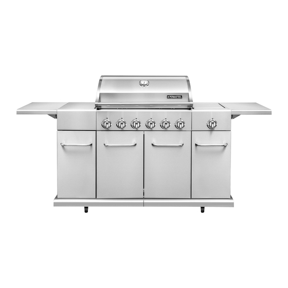
6B Entertainment Grill
For Outdoor Use Only
1. Do not store or use gasoline or
other flammable liquids or vapors in
the vicinity of this or any other
appliance.
2. An LP cylinder not connected
for use shall not be stored in the
vicinity of this or any other
appliance.
1
MODEL: PG-40612SOLE
WARNING
ITEM 0714341
Publicidad
Capítulos
Tabla de contenido
Solución de problemas

Manuales relacionados para PERMASTEEL PG-40612SOLE

Resumen de contenidos para PERMASTEEL PG-40612SOLE
- Página 1 ITEM 0714341 6B Entertainment Grill MODEL: PG-40612SOLE For Outdoor Use Only DANGER WARNING If you smell gas: 1. Do not store or use gasoline or 1. Shut off gas to the appliance. other flammable liquids or vapors in 2. Extinguish any open flame.
-
Página 2: Tabla De Contenido
TABLE OF CONTENTS Package Contents..........................3-4 Hardware Contents........................5 Message to users........................6 Safety symbols ......................... 6 Caution............................7 NG Conversion Kit........................7 Gas Connection ........................8-9 Grill Lighting Instruction......................10 Before assembly........................11-14 Assembly or Instructions ....................15-36 Operating Instructions ......................37 Care and Maintenance ....................... 38 Leak Testing........................ -
Página 3: Package Contents
PACKAGE CONTENTS... - Página 4 PACKAGE CONTENTS PART DESCRIPTION QUANTITY PART NO. PART DESCRIPTION QUANTITY PART NO. Temperature Gauge 30800207 Side burner 60600219 Temp Gauge Bezel 30800208 Igniter Wire, Side Burner 61000218 Lid(Stainless Steel) 61000201 Fascia, right Side Shelf 61000219 Rotate Rod, Lid 61000001 Right side shelf bracket 61000010 Logo 61000002...
-
Página 5: Hardware Contents
HARDWARE CONTENTS M6 ×12mm M5 Flat M4 x 10 mm M6 x 17mm M6 Nut shoulder Washer Screw Screw screw Qty. 5 Qty. 4 Qty. 97 Qty. 8 Qty. 4 M6 x 40 mm M6 Flat M5 × 10 M6 × 13 Battery Screw Washer... -
Página 6: Message To Users
MESSAGE TO OUR USERS Thank you for your purchase of our BBQ Gas Grill. We sincerely wish you will enjoy using our fine products. Please read this User’s Manual in its entirety before using the grill. Please contact our customer service at (888)-287-0735 if you have any questions. Please read this User’s Manual carefully. -
Página 7: Caution
Tools Required for Assembly (not included): Wrench, Phillips Screwdriver, Straight screwdriver, Nipper pliers Natural Gas Conversion Kit (Sold separately) To purchase Natural Gas Conversion Parts please call Permasteel at 1-888-287-0735, 8 a.m. - 5 p.m., PST, Monday - Friday. Natural Gas Conversion Kit (Manufacturer Model PG-40610S0N-TRQ01) Your grill can be converted to natural gas with this conversion kit by a qualified gas technician only. -
Página 8: Gas Connection
GAS CONNECTION ONLY USE THE REGULATOR AND HOSE ASSEMBLY PROVIDED WITH THIS GRILL. RE- PLACEMENT PRESSURE REGULATORS AND HOSE ASSEMBLIES MUST BE THOSE SUP- PLIED BY THE MANUFACTURER The installation of this appliance must conform with local codes or, in the absence of local codes, with either the National Fuel Gas Code, ANSI Z223. - Página 9 GAS CONNECTION CONNECT THE REGULATOR TO THE LP TANK VERY IMPORTANT: - THE REGULATOR SHALL NOT BE IN A LOCATION THAT WILL ATTAIN A TEMPERATURE ABOVE 125 degree (51.C) - THE REGULATOR SHALL INCORPORATE A PRESSURE RELIEF VALVE OR OVERPRESSURE DEVICE. - THE INLET OF THE PRESSURE REGULATOR SHALL BE FITTED TO CONNECT THE TYPE I CONNECTION OF THE TANK VALVE PER ANSIZ21.81.
-
Página 10: Grill Lighting Instruction
GRILL LIGHTING INSTRUCTION VERY IMPORTANT: ALWAYS INSPECT THE HOSE PRIOR TO EACH USE. BEFORE LIGHTING: Inspect the gas supply hose before turning the gas “ON”. If there is evidence of cuts, wear, or abrasion, it must be replaced before use. The replacement hose assembly must be that specified by the manufacturer. -
Página 11: Before Assembly
BEFORE ASSEMBLY READ AND FOLLOW THE INSTRUCTIONS BELOW TO CORRECTLY UNPACK GRILL PARTS FROM SHIPPING BOX. 1. Once you open the top of the shipping box, grasp box by the top flaps and raise it up and away from the packaged grill. Take out the Hardware Pack, manual, back panel, also take out right cabinet shelf from side. - Página 12 BEFORE ASSEMBLY 2. Continue to remove the left panel of left cabinet, right bottom self, tank bottom self, trash can tray, right foldable shelf. Next, then remove the left and back panel of left cabinet, left and right cabinet door, front and back bottom support bar.
- Página 13 BEFORE ASSEMBLY 3. Remove the fascia, left and right side shelf, door bracket of left and right cabinet, tank baffle, right panel of right cabinet, left and right door of main cabinet. With the aid of an assistant, lift the grill head out of the bottom styrofoam piece.
- Página 14 BEFORE ASSEMBLY 4. Open grill lid, and take out the small boxes packed within the grill head. Remove all packing materials, and remove all parts from boxes.
-
Página 15: Assembly Or Instructions
ASSEMBLY INSTRUCTIONS 1. Turn both D39&D43 bottom shelves upside down. Align and connect them with (5) M6×13 Screws and M6 Nuts as shown. Tighten securely. Hardware Used M6 x 13 mm Screw M6 Nut 2. Insert the two D44&D40 bottom shelf support bars through the square holes at middle of bottom shelf as shown. - Página 16 ASSEMBLY INSTRUCTIONS 4. Turn bottom shelf upside down. Attach D41&D42 casters to bottom shelf with (16) M6x13 screws. IMPORTANT: Install each caster into the correct position as shown in the figure below. Hardware Used M6 x 13 mm Screw x 16 5.
- Página 17 ASSEMBLY INSTRUCTIONS 7. Attach D02 back panel to bottom shelf and side panels with (8) M4x10 screws. Hardware Used M4 x 10 mm Screw 8. Attach the D30 tank tray on bottom shelf with (4) M6×13 screws. Hardware Used M6 x 13 mm Screw 9.
- Página 18 ASSEMBLY INSTRUCTIONS 10. Attach D11 cart support angle bars with (8) M4x10 screws. Hardware Used M4 x 10 mm Screw 11. Attach D01 back panel of left cabinet to bottom shelf and main cabinet left panel with (5) M4x10 screw. Hardware Used M4 x 10 mm Screw 12.
- Página 19 ASSEMBLY INSTRUCTIONS 13. Attach D06 left panel of left cabinet to bottom shelf and back panel with (6) M4x10 screws. Hardware Used M4 x 10 mm Screw 14. Attach D03 back panel of right cabinet to bot- tom shelf and main cabinet right panel with (5) M4x10 screws.
- Página 20 ASSEMBLY INSTRUCTIONS 16. Insert D17 right cabinet tank baffle A into place, and secure with (4) M4x10 screws as shown. Hardware Used M4 x 10 mm Screw 17. Insert D25 left cabinet door bracket into place as shown. Note: Be sure to position bracket with magnets at bottom.
- Página 21 ASSEMBLY INSTRUCTIONS 19. Attach D23 right cabinet magnet box to main cabinet side panel with (2) M4x10 screws. Hardware Used M4 x 10 mm Screw 20. Attach D23 left cabinet magnet box to main cabinet side panel with (2) M4x10 screws. Hardware Used M4 x 10 mm Screw 21.
- Página 22 ASSEMBLY INSTRUCTIONS 22. Attach D15 right ignition module box to main Right Ignition module cabinet right panel with (4) M4x10 screws. Also attach D10 ignition wire clip to panel with (1) M4x10 screw as shown. Hardware Used M4 x 10 mm Screw 23.
- Página 23 ASSEMBLY INSTRUCTIONS 25. This step requires two people to lift and position A10 grill head onto cart. Remove tie wraps securing regulator hose and ignition wires to underside of grill head. Pull hose out to side of main cabinet. Carefully lower the firebox onto the cart.
- Página 24 ASSEMBLY INSTRUCTIONS 28. Attach B04 fascia to B03 left side shelf with (2) M5 x 10 mm Screw and (2) M5 Flat Washer. Hardware Used M5 x 10 mm Screw M5 Flat Washer 29. Place assembly left side shelf on top of left cabinet as shown.
- Página 25 ASSEMBLY INSTRUCTIONS 31. Attach left shelf to cabinet with (7) M4 x 10 mm screws, align to correct position then tighten the screws. Hardware Used M4 x 10 mm Screw 32. Attach the two labeled “LEFT” B02 folding side shelf support brackets to the outer panel of left cabinet with (4) M6x17 screws.
- Página 26 ASSEMBLY INSTRUCTIONS 34. Attach right side shelf fascia C09 to right side shelf C04 with (2) M5x10 screws and (2) M5 flat washers as shown. Hardware Used M5 x 10 mm Screw M5 Flat Washers 35. Place right side shelf on top of right cabinet as shown.
- Página 27 ASSEMBLY INSTRUCTIONS 37. Attach right shelf to cabinet with (7) M4 x 10 mm Screw, align the right position then tighten the screws. Hardware Used M4 x 10 mm Screw 38. Attach the two labeled “RIGHT” folding side shelf support brackets C10 to the outer panel of right cabinet with (4) M6x17 screws.
- Página 28 ASSEMBLY INSTRUCTIONS 40. Loosen side burner C05&C06 in side shelf by unscrewing and removing the two front screws holding the burner in place.Note: Do not loosen electrode screw. Hardware Used NONE. 41. Remove the (2) pre-installed M4 × 10 screw from gas valve A19 and set them aside.
- Página 29 ASSEMBLY INSTRUCTIONS 43. Attach bezel A32 to facial and valve face with the installed screws .First attach one side key hole of bezel to the screw, then attach the other one to the other screw. Make sure the black mark face up. Tighten the 2 screws.
- Página 30 ASSEMBLY INSTRUCTIONS 46. Classify the six wires as shown. Wires for Right Ignition Module Hardware Used NONE. Side burner Wire A13A14A15 Large Black Wire Large Red tip Wire Small Black Wire 47. A--Insert the four small black wires as shown. (no orders of the wires) B--Insert the large red tip wire as shown.
- Página 31 ASSEMBLY INSTRUCTIONS 49. Unscrew the igniter cap from D09 right ignition mod- ule. Insert 1 AA battery into module with positive (+) facing outward. Screw igniter cap back onto module. Hardware Used Battery 50. Classify the six wires as shown. Wires for left Ignition Module Hardware Used NONE.
- Página 32 ASSEMBLY INSTRUCTIONS 52. Gather the six wires together and push them into the left ignition wire clip D10 to store them neatly out of the way. Hardware Used NONE. 53. Unscrew the igniter cap from D09 left ignition module. Insert 1 AA battery into module with posi- tive (+) facing outward.
- Página 33 ASSEMBLY INSTRUCTIONS 55. A--For each door, insert the bottom hinge pin into the hole in the cart bottom shelf. B--Push the top hinge pin down into the door, align it with the top hinge pin hole. C--Let the pin pop back up, securing the door in position.
- Página 34 ASSEMBLY INSTRUCTIONS 58. A--For each door, insert the bottom hinge pin into the hole in the cart bottom shelf. B--Push the top hinge pin down into the door, align it with the top hinge pin hole. C--Let the pin pop back up, securing the door in position.
- Página 35 ASSEMBLY INSTRUCTIONS 61. Slide the drip cup A35 into the drip tray assembly A34 as shown. Hardware Used NONE. 62. Insert the Match Holder Bracket D05 into the hole in rear of main cabinet right side panel as shown. Use it to attach match holder D04 to grill. Hardware Used NONE.
- Página 36 ASSEMBLY INSTRUCTIONS 64. Place the gas tank on tank tray. Turn the guide rail plate D32 clockwise rotation of 230 degree, then the tank tray can be pulled out; counter-clockwise the guide rail plate D32 for 230 degree then it can be fixed. Hardware Used Unfixed Fixed...
-
Página 37: Operating Instructions
OPERATING INSTRUCTIONS • TOTAL GAS CONSUMPTION: Total gas consumption (per hour) of PG-40612SOLE grill with all burners on “HI”: Main Burners 60,000 Btu/hr Side Burner 13,000 Btu/hr Total 73,000 Btu/hr CAUTION • Clean the grill often. A grease fire that may damage the grill may occur if the grill has not been cleaned frequently. -
Página 38: Care And Maintenance
CARE AND MAINTENANCE • MAINTENANCE 1) Keep the grill area clear and free from combustible materials, gasoline and other flammable vapors and liquids. 2) Keep the holes in the three sides of the cart clear and free from debris, thus ensure the flow of combustion and ventilation air is unobstructed. -
Página 39: Leak Testing
LEAK TESTING GENERAL Although all gas connections on the grill are leak tested at the factory prior to shipment, a complete gas tightness check must be performed at the installation site due to possible mis- handling in shipment, or excessive pressure unknowingly being applied to the unit. Periodi- cally check the whole system for leaks, or immediately check if the smell of gas is detected. -
Página 40: Final Installation Checklist
LEAK TESTING SAFETY TIPS: 1) ALWAYS CHECK FOR LEAKS AFTER EVERY LP TANK CHANGE. 2) ALWAYS CHECK FOR LEAKS BEFORE EACH USE. 3) USE LONG BBQ TOOL TO AVOID BURNS. 4) CHECK ALL GAS SUPPLY FITTINGS FOR LEAKS BEFORE EACH USE. IT IS HANDY TO KEEP A SPRAY BOTTLE OF SOAPY WATER NEAR THE SHUT-OFF VALVE OF THE GAS SUPPLY LINE. -
Página 41: Troubleshooting
TROUBLESHOOTING PROBLEM POSSIBLE CAUSE CORRECTIVE ACTION GAS ISSUES: • Trying to light wrong burner. • See instructions on control panel and in Use and Care section. • Burner not engaged with control • Make sure valves are positioned inside valve. of burner tubes. - Página 42 TROUBLESHOOTING PROBLEM POSSIBLE CAUSE CORRECTIVE ACTION ELECTRONIC IGNITION: • See Section I of Electronic Ignition Burner(s) will not • No spark, no ignition noise. System. light using igniter. (See Electronic • No spark, some ignition noise. • See Section II of Electronic Ignition Ignition Trouble- System.
-
Página 43: Warranty
WARRANTY PERMASTEEL WARRANTY WITH PROOF OF SALE, the following warranty coverage applies when this gas grill is correctly assembled, operated and maintained according to all supplied instructions. FOR ONE YEAR from the date of sale this gas grill is warranted against defects in material or workmanship. -
Página 44: Replacement Part List
REPLACEMENT PARTS LIST For replacement parts, call our customer service department at 1-888-287-0735, 9 a.m. - 5 p.m., PST, Monday - Friday. NOTE: All the parts list are availbale to order by customer, please refer to the part list above for reference. - Página 45 TABLA DE CONTENIDO Contenidos del paquete......................46-47 Contenido del hardware......................48 Mensaje a los usuarios......................49 Símbolos de seguridad........................49 Precaución............................50 Kit de conversión NG........................50 Conexión de gas ........................51-52 Instrucciones de iluminación de la parrilla................53 Antes del montaje......................54-57 Asamblea o Instrucciones .....................58-79 Instrucciones de operación ....................
-
Página 46: Contenidos Del Paquete
CONTENIDOS DEL PAQUETE... - Página 47 CONTENIDOS DEL PAQUETE PARTE DESCRIPCIÓN CANTIDAD PARTE NO. PARTE DESCRIPCIÓN CANTI- PARTE NO. Indicador de temperatura 30800207 quemador lateral 60600219 Bisel de indicador de temperatura 30800208 Cable del encendedor, quemador lateral 61000218 Tapa (acero inoxidable) 61000201 Fascia, estantería lateral derecha 6100219 Girar la varilla, tapa 61000001...
-
Página 48: Contenido Del Hardware
CONTENIDO DEL HARDWARE Tornillo de M5 Lavadora M4 x 10 mm M6 x 17mm Tuerca M6 hombro M6 × plana Tornillo Tornillo 12mm Qty. 5 Qty. 4 Qty. 97 Qty. 8 Qty. 4 M6 x 40 mm M6 Lava- M5 × 10 M6 ×... -
Página 49: Mensaje A Nuestros Usuarios
MENSAJE A NUESTROS USUARIOS Gracias por su compra de nuestra parrilla de gas para barbacoa. Deseamos sincera- mente que usted goce el usar de nuestros productos finos. Por favor, lea este manual del usuario en su totalidad antes de usar la parrilla. Por favor, póngase en contacto con nuestro servicio de atención al cliente al (888) -287-0735 si tiene alguna pregunta. -
Página 50: Precaución
Llave inglesa, destornillador Phillips, destornillador recto, alicates Nipper Kit de conversión de gas natural (se vende por Para comprar Piezas de Conversión de Gas Natural, llame a Permasteel al 1-888-287-0735, de 8:00 a.m. - 5 p.m., PST, de lunes a viernes. -
Página 51: Conexión De Gas
CONEXION DE GAS SOLAMENTE USE EL MONTAJE DEL REGULADOR Y LA MANGUERA SUMINISTRADO CON ESTA PARRILLA. LOS REGULADORES DE PRESIÓN DE REEMPLAZO Y LOS CONJUNTOS DE MANGUERAS DEBEN SER LOS SUMINISTRADOS POR EL FABRICANTE La instalación de este aparato debe cumplir con los códigos locales o, en ausencia de códigos locales, con el Código Nacional de Gas Combustible, ANSI Z223. - Página 52 CONEXION DE GAS CONECTAR EL REGULADOR AL TANQUE DE LP MUY IMPORTANTE: - EL REGULADOR NO ESTARÁ EN UNA UBICACIÓN QUE TEMPERATURA SUPERIOR A 125 grados (51.C) - EL REGULADOR INCORPORARÁ UNA VÁLVULA DE ALIVIO DE PRESIÓN O DISPOSITIVO DE SOBREPRESION. - LA ENTRADA DEL REGULADOR DE PRESIÓN SE DEBERÁ...
-
Página 53: Instrucciones De Iluminación De La Parrilla
INSTRUCCIÓN DE ILUMINACIÓN DE LA PARRILLA MUY IMPORTANTE: SIEMPRE INSPECCIONE LA MANGUERA ANTES DE CADA USO. ANTES DE ILUMINAR: Inspeccione la manguera de suministro de gas antes de encender el gas. Si hay evidencia de cortes, desgaste o abrasión, debe ser reemplazado antes de su uso. El reemplazo el conjunto de la manguera debe ser el especificado por el fabricante. -
Página 54: Antes De Asamblea
ANTES DE ASAMBLEA LEA Y SIGA LAS INSTRUCCIONES ABAJO PARA DESEMBALAR CORRECTAMENTE LAS PIE- ZAS DE LA PARRILLA DE LA CAJA DE ENVÍO. 1. Una vez que abra la parte superior de la caja de envío, agarre la caja por las aletas superiores y levántela y lejos de la parrilla envasada. - Página 55 ANTES DE ASAMBLEA 2. Continúe quitando el panel izquierdo del armario izquierdo, el fondo inferior derecho, el fondo del tanque, la bandeja de la papelera, el estante plegable derecho. A continuación, retire el panel izquierdo y posterior del armario izquierdo, la puerta izquierda y derecha del armario, la barra de soporte inferior delantera y trasera.
- Página 56 ANTES DE ASAMBLEA 3. Retire la fascia, el estante izquierdo y derecho, el soporte de la puerta del armario izquierdo y derecho, el deflector del tanque, el panel derecho del armario derecho, la puerta izquierda y dere- cha del gabinete principal. Con la ayuda de un asistente, levante la cabeza de la parrilla fuera de la pieza de espuma de poliestireno inferior.
- Página 57 ANTES DE ASAMBLEA 4. Abra la tapa de la parrilla y saque las cajas pequeñas que están dentro de la cabeza de la par- rilla. Retire todos los materiales de embalaje y retire todas las piezas de las cajas.
-
Página 58: Asamblea O Instrucciones
INSTRUCCIONES DE MONTAJE 1. Gire los dos estantes inferiores D39 y D43 boca abajo. Alinee y conéctelos con (5) tornillos M6 × 13 y tuercas M6 como se muestra. Apriete firme- mente. Hardware usado M6 x 13 mm Tornillo Tuerca M6 2. - Página 59 INSTRUCCIONES DE MONTAJE 4. Gire el estante inferior boca abajo. Conecte las ruedas D41 y D42 a la plataforma inferior con (16) tornillos M6x13. IMPORTANTE: Instale cada lanzador en la posición correcta como se muestra en la figura siguiente. Hardware usado M6 x 13 mm Tornillo x 16 5.
-
Página 60: Hardware Usado
INSTRUCCIONES DE MONTAJE 7. Fije el panel trasero D02 a la repisa inferior y los paneles laterales con (8) tornillos M4x10. Hardware usado M4 x 10 mm Tornillo 8. Sujete la bandeja del tanque D30 en el estante inferior con (4) tornillos M6 × 13. Hardware usado M6 x 13 mm Tornillo 9. - Página 61 INSTRUCCIONES DE MONTAJE 10. Fije las barras de ángulo de soporte del carro D11 con (8) tornillos M4x10. Hardware usado M4 x 10 mm Tornillo 11. Sujete el panel trasero D01 del armario izquier- do al estante inferior y al panel izquierdo del arma- rio principal con (5) tornillo M4x10.
- Página 62 INSTRUCCIONES DE MONTAJE 13. Fije el panel izquierdo D06 del armario izqui- erdo a la repisa inferior y los paneles laterales con (6) tornillos M4x10. Hardware usado M4 x 10 mm Tornillo 14. Fije el panel trasero D03 del armario derecho al estante inferior y al panel derecho del armario principal con (5) Tornillos M4x10.
- Página 63 INSTRUCCIONES DE MONTAJE 16. Inserte el deflector del tanque A del gabinete derecho D en su lugar y asegúrelo con (4) tornillos M4x10 como se muestra. Hardware usado M4 x 10 mm Tornillo 17. Inserte el soporte izquierdo de la puerta del gabinete D25 en su lugar como se muestra.
- Página 64 INSTRUCCIONES DE MONTAJE 19. Fije los imanes de la puerta derecha del arma- rio D23 al panel lateral del armario principal con (2) tornillos M4x10. Hardware usado M4 x 10 mm Tornillo 20. Fije los imanes de la puerta izquierda del arma- rio D23 al panel lateral del armario principal con (2) tornillos M4x10.
- Página 65 INSTRUCCIONES DE MONTAJE 22. Fije la caja del módulo de encendido derecho D15 Right Ignition module al panel derecho del armario principal con (4) tornillos M4x10. También coloque el clip de alambre de encendido D10 en el panel con (1) tornillo M4x10 como se muestra. Hardware usado M4 x 10 mm Tornillo 23.
- Página 66 INSTRUCCIONES DE MONTAJE 25. Este paso requiere dos personas para levantar y colocar la cabeza de la parrilla A10 en el carro. Retire las abrazad- eras que sujetan la manguera del regulador y los cables de encendido a la parte inferior de la cabeza de la parrilla. Tire de la manguera hacia afuera al lado del gabinete principal.
- Página 67 INSTRUCCIONES DE MONTAJE 28. Fije el tablero B04 al estante izquierdo B03 con (2) tornillo M5 x 10 mm y (2) arandela plana M5. Hardware usado M5 x 10 mm Tornillo M5 Lavadora plana 29. Coloque el estante del lado izquierdo del ens- amblaje en la parte superior del armario izquierdo como se muestra.
- Página 68 INSTRUCCIONES DE MONTAJE 31. Fije la repisa izquierda al armario con (7) tor- nillos M4 x 10 mm, alinee la posición derecha y apriete los tornillos. Hardware usado M4 x 10 mm Tornillo 32. Fije los dos soportes de soporte laterales plegables B02 marcados “LEFT”...
- Página 69 INSTRUCCIONES DE MONTAJE 34. Fije la fascia C09 del estante lateral derecho al estante C04 derecho con (2) tornillos M5x10 y (2) arandelas planas M5 como se muestra. Hardware usado M5 x 10 mm Tornillo Arandelas planas M5 35. Coloque el estante derecho sobre la parte su- perior del armario derecho como se muestra.
- Página 70 INSTRUCCIONES DE MONTAJE 37. Fije el estante derecho al armario con (7) M4 x 10 mm Tornillo, alinee la posición derecha y apriete los tornillos. Hardware usado M4 x 10 mm Tornillo 38. Sujete los dos soportes de soporte de estantería lat- eral plegables “RIGHT”...
- Página 71 INSTRUCCIONES DE MONTAJE 40. Suelte el quemador lateral C05 y C06 en el estante lateral desenroscando y quitando los dos tornillos delanteros que sujetan el quemador en su lugar. Nota: No afloje el tornillo del electrodo. Hardware usado NINGUNA. 41. Retire el tornillo M4 × 10 preinstalado de la válvula de gas A19 y déjelo a un lado.
- Página 72 INSTRUCCIONES DE MONTAJE 43. Fije el bisel A32 a la cara facial y de la válvula con los tornillos instalados. Primero coloque un ori- ficio lateral del bisel en el tornillo y, a continuación, conecte el otro al otro tornillo. Asegúrese de que la marca negra esté...
- Página 73 INSTRUCCIONES DE MONTAJE 46. Clasifique los seis cables como se muestra. Wires for Right Ignition Module Hardware usado NINGUNA. Small Black Wire A13A14A15 Large Black Wire Large Red tip Wire Small Black Wire 47. A - Inserte los cuatro cables negros pequeños como se muestra.
- Página 74 INSTRUCCIONES DE MONTAJE 49. Desenrosque la tapa del encendedor del módulo de encendido derecho D09. Inserte 1 pila AA en el módulo con positivo (+) hacia afuera. Enrosque la tapa del en- cendedor en el módulo. Hardware usado Batería 50. Clasifique los seis cables como se muestra. Alambres para el módulo de encendido izquierdo Hardware usado...
- Página 75 INSTRUCCIONES DE MONTAJE 52. Reunir los seis cables juntos y empujarlos en el clip de alambre de encendido izquierdo D10 para guardarlos ordenadamente fuera del camino. Hardware usado NINGUNA. 53. Desenrosque la tapa del encendedor del módu- lo de encendido izquierdo D09. Inserte 1 pila AA en el módulo con el positivo (+) mirando hacia fuera.
- Página 76 INSTRUCCIONES DE MONTAJE 55. A - Para cada puerta, inserte el pasador de bisagra inferior en el agujero en el estante del fondo del carro. B - Empuje el perno de la bisagra superior hacia abajo en la puerta, alinearlo con el orificio superior del pasador de la bisagra.
- Página 77 INSTRUCCIONES DE MONTAJE 58. A - Para cada puerta, inserte el pasador de bisagra inferior en el agujero en el estante del fondo del carro. B - Empuje el perno de la bisagra superior hacia abajo en la puerta, alinearlo con el orificio superior del pasador de la bisagra. C - Deje que el perno vuelva a subir, asegurando la puerta posición.
- Página 78 INSTRUCCIONES DE MONTAJE 61. Deslice la copa de goteo A35 en el conjunto de la bandeja de goteo A34 como se muestra. Hardware usado NINGUNA. 62. Inserte el Soporte del Soporte de Combate D05 en el orificio en la parte posterior del panel del lado derecho del armario principal como se muestra.
- Página 79 INSTRUCCIONES DE MONTAJE 64. Coloque el tanque de gas en la bandeja del tanque. Gire la placa del carril de guía D32 en el sentido de las agujas del reloj de 230 grados, entonces la bandeja del tanque se puede sacar; en sentido contrario a las agujas del reloj la placa del carril de guía D32 para 230 grados, entonces se puede fijar.
-
Página 80: Instrucciones De Operación
INSTRUCCIONES DE OPERACIÓN • CONSUMO TOTAL DE GAS: Consumo total de gas (por hora) de la parrilla PG-40612SOLE con todos los que- madores en “HI”: Quemadores principales 60.000 Btu / hr Quemador lateral 13.000 Btu / h Total 73.000 Btu / h PRECAUCIÓN... -
Página 81: Cuidado Y Mantenimiento
CUIDADO Y MANTENIMIENTO • MANTENIMIENTO 1) Mantenga el área de la parrilla libre y libre de materiales combustibles, gasolina y otros vapores y líquidos inflam- ables. 2) Mantenga los orificios en los tres lados del carro despejados y libres de escombros, así asegúrese de que el flujo de aire de combustión y ventilación no esté... -
Página 82: Prueba De Fugas
PRUEBA DE FUGAS GENERAL Aunque todas las conexiones de gas en la parrilla se prueban con fugas en la fábrica antes del embarque, debe realizarse una comprobación completa de hermeticidad en el lugar de instalación debido a posibles manipulaciones incorrectas en el envío oa una presión exce- siva sin saberlo aplicada a la unidad. -
Página 83: Lista De Verificación Final De La Instalación
PRUEBA DE FUGAS CONSEJOS DE SEGURIDAD: 1) SIEMPRE CONSULTE LAS FUGAS DESPUÉS DE CADA VARIACIÓN DE TANQUE LP. 2) SIEMPRE CONSULTE LAS FUGAS ANTES DE CADA USO. 3) UTILICE LA HERRAMIENTA LARGA DEL Bbq PARA EVITAR QUEMADURAS. 4) VERIFIQUE TODAS LAS FITAS DE SUMINISTRO DE GAS PARA FUGAS ANTES DE CADA USO.ES HANDY PARA MANTENER UNA BOTELLA DE AGUA SOAPY CERCA DELVÁLVULA DE CIERRE DE LA LÍNEA DE SUMINISTRO DE GAS. -
Página 84: Causa Posible
TROUBLESHOOTING PROBLEMA CAUSA POSIBLE ACCIÓN CORRECTIVA PROBLEMAS DE GAS: •Consulte las instrucciones en el panel de • Intentar encender el quemador control y en la sección Uso y cuidado. incorrecto. • Asegúrese de que las válvulas estén colo- cadas dentro de los tubos del quemador. •... -
Página 85: Solución De Problemas
TSOLUCIÓN DE PROBLEMAS PROBLEMA CAUSA POSIBLE ACCIÓN CORRECTIVA IGNICIÓN ELECTRÓNICA: •Véase la Sección I del Sistema de En- Los quemadores • Sin chispa, sin ruido de ignición. cendido Electrónico. no se encenderán usando el encend- • Ninguna chispa, algún ruido de •... -
Página 86: Garantía
GARANTÍA GARANTÍA PERMASTEEL CON PRUEBA DE VENTA, la siguiente cobertura de garantía se aplica cuando esta parrilla de gas está cor- rectamente montada, operada y mantenida de acuerdo con todas las instrucciones suministradas. POR UN AÑO a partir de la fecha de venta esta parrilla de gas está garantizada contra defectos de material o mano de obra. -
Página 87: Lista De Piezas De Repuesto
LISTA DE PIEZAS DE REPUESTO Para piezas de repuesto, llame a nuestro departamento de servicio al cliente al 1-888-287-0735, de 9:00 a.m. - 5 p.m., PST, de lunes a viernes. NOTA: Toda la lista de piezas está disponible para ordenar por el cliente, por favor refiérase a la lista de piezas arriba para referencia. - Página 88 PERMASTEEL, INC. 100 EXCHANGE PLACE, UNIT A, POMONA, CA 91768 TEL: (888)-287-0735 FAX: (909)-287-0733 EMAIL: SERVICE@PERMASTEEL.NET...