Tabla de contenido
Publicidad
Idiomas disponibles
Idiomas disponibles
Enlaces rápidos
INSTALLATION INSTRUCTIONS FOR PART 99-3303
Chevrolet/Pontiac 2004-2009
KIT FEATURES
• DIN head unit provision with
driver information center (DIC)
• ISO DIN head unit provision with
driver information center (DIC)
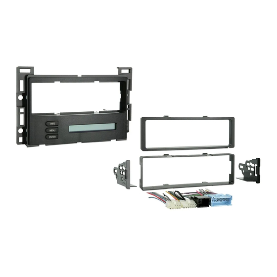
KIT COMPONENTS
• A) Radio Housing • B) ISO brackets • C) ISO trim plate • D) DIN Spacer • E) Wire harness
A
D
E
• Phillips screwdriver • Socket wrench • Flat blade screwdriver • Cutting tool (Cobalt only)
APPLICATIONS
99-3303
B
WIRING & ANTENNA CONNECTIONS (sold separately)
Wiring Harness:
• Included
Antenna Adapter:
• 40-GM10 - GM antenna adapter 1988-up
TOOLS REQUIRED
• Wire cutters • Wire strippers
METRA. THE WORLD'S BEST KITS.™
1-800-221-0932
© COPYRIGHT 2004-2011 METRA ELECTRONICS CORPORATION
C
metraonline.com
Publicidad
Capítulos
Tabla de contenido

Manuales relacionados para Metra 99-3303


Resumen de contenidos para Metra 99-3303
- Página 1 INSTALLATION INSTRUCTIONS FOR PART 99-3303 APPLICATIONS Chevrolet/Pontiac 2004-2009 99-3303 KIT FEATURES • DIN head unit provision with driver information center (DIC) • ISO DIN head unit provision with driver information center (DIC) KIT COMPONENTS • A) Radio Housing • B) ISO brackets • C) ISO trim plate • D) DIN Spacer • E) Wire harness WIRING &...
-
Página 2: Tabla De Contenido
Final Assembly ....................9 – Operation of the 99-3303 ..................10 CAUTION: Metra recommends disconnecting the negative battery terminal before beginning any installation. All accessories, switches, and especially air bag indicator lights must be plugged in before reconnecting the battery or cycling the ignition. -
Página 3: Dash Disassembly
Dash Disassembly 99-3303 Chevrolet Malibu 2004-2007 Malibu Classic 2008 1. Unclip and remove wood grain/painted trim pieces from both sides of steering wheel. (Figure A) 2. Unclip and remove side panel from driver’s side of dash with door open and remove (2) 7 mm screws. - Página 4 Dash Disassembly 99-3303 Chevrolet Malibu 2004-2007 Malibu Classic 2008 5. Unclip and remove side panel from passenger side of dash with door open and remove (2) 7 mm screws from behind panel. (Figure E) 6. Remove (2) 7 mm screws from bottom...
- Página 5 Dash Disassembly 99-3303 Pontiac G6 2005-2009 1. Open glove box and remove (6) screws from outer edge then unclip and remove box. (Figure A) 2. Remove (4) screws from panel below steering column and unclip and remove panel. (Figure B) 3.
-
Página 6: Chevrolet Cobalt 2005-2006
Dash Disassembly 99-3303 Chevrolet Cobalt 2005-2006 1. Unclip and remove trim panel from above glove box. (Figure A) 2. Unclip upper edge of panel below steering column and let hang. Not necessary to remove completely. (Figure B) 3. Unclip and remove small trim panel to right of ignition switch. -
Página 7: Kit Assembly
(Figure A) (Figure C) 3. Locate the factory wiring harness in the dash. Metra recommends using the proper mating adapter from Metra or AXXESS. Re-connect the negative battery terminal and test the unit for proper operation. 4. Reassemble dash in reverse order of disassembly. -
Página 8: Iso Din Head Unit Provision
Housing. (Figure B) 4. Locate the factory wiring harness in the dash. Metra recommends using the (Figure A) proper mating adapter from Metra or AXXESS. Re-connect the negative battery terminal and test the unit for proper operation. 5. Reassemble dash in reverse order of disassembly. -
Página 9: Final Assembly
*Note: When Black a wire is not present, ground radio to vehicle chassis. All colors may not be present on all leads due to manufacturer’s specifications. 2. Plug the clear 10-way and 12-way connectors into the back of the 99-3303 housing. 3. Connect the Light Blue 24-way connector to the factory 24-way harness. -
Página 10: Operation Of The 99-3303
Final Assembly 99-3303 Operation of the 99-3303 Setting and Adjustment mode There is a Settings and Adjustments mode available for the individualized adjustment of the contrast of the display, brightness of the display and backlighting, OnStar volume, and the button backlighting color. - Página 11 Notes...
- Página 12 INSTALLATION INSTRUCTIONS FOR PART 99-3303 METRA. THE WORLD’S BEST KITS.™ metraonline.com 1-800-221-0932 © COPYRIGHT 2004-2011 METRA ELECTRONICS CORPORATION...
- Página 13 INSTRUCCIONES DE INSTALACIÓN PARA LA PIEZA 99-3303 APLICACIONES Chevrolet/Pontiac 2004-2009 99-3303 CARACTERÍSTICAS DEL KIT • Provisión de unidad central DIN con centro de información del conductor (DIC) • Provisión de unidad central ISO DIN con centro de información del conductor (DIC) COMPONENTES DEL KIT •...
- Página 14 – Operación del 99-3303 ................9 PRECAUCIÓN: Metra recomienda desconectar el terminal negativo de la batería antes de comenzar cualquier instalación. Todos los accesorios, interruptores y, especialmente, las luces indicadoras de airbag deben estar enchufados antes de volver a conectar la batería o comenzar el ciclo de ignición.
-
Página 15: Desmontaje Del Tablero
Desmontaje del tablero 99-3303 Chevrolet Malibu 2004-2007 Malibu Classic 2008 1. Desenganche y retire las piezas de moldura de veta de madera/pintadas de ambos lados del volante. (Figura A) 2. Desenganche y retire el panel lateral del lado del conductor del tablero con la puerta abierta y retire los (2) tornillos de 7 mm. - Página 16 Desmontaje del tablero 99-3303 Chevrolet Malibu 2004-2007 Malibu Classic 2008 5. Desenganche y retire el panel lateral del lado del conductor del tablero con la puerta abierta y retire los (2) tornillos de 7 mm detrás del panel. (Figura E) 6.
- Página 17 Desmontaje del tablero 99-3303 Pontiac G6 2005-2009 1. Abra la guantera y retire los (6) tornillos del borde exterior, luego desenganche y retire la guantera. (Figura A) 2. Retire los (4) tornillos del panel debajo de la columna de dirección y desenganche y retire el panel.
-
Página 18: Chevrolet Cobalt 2005-2006
Desmontaje del tablero 99-3303 Chevrolet Cobalt 2005-2006 1. Desenganche y retire el panel de la moldura de arriba de la guantera. (Figura A) 2. Desenganche el borde superior del panel debajo de la columna de dirección y déjelo colgando. No es necesario retirar el panel por completo. -
Página 19: Ensamble Del Kit
(Figura C) 3. Ubique el arnés del cableado de fábrica en el tablero. Metra recomienda usar el adaptador de acoplamiento adecuado de Metra o AXXESS. Vuelva a conectar el terminal negativo de la batería y pruebe la unidad para verificar que funcione correctamente. -
Página 20: Provisión De Unidad Central Iso Din
(Figura B) 4. Ubique el arnés del cableado de fábrica (Figura A) en el tablero. Metra recomienda usar el adaptador de acoplamiento adecuado de Metra o AXXESS. Vuelva a conectar el terminal negativo de la batería y pruebe la unidad para verificar que funcione correctamente. -
Página 21: Ensamble Del Final
99-3303 Ensamble del final 1. Realizar las conexiones con Metra/EIA código de cableado tabla de, se muestra a continuación, y las instrucciones incluidas con la unidad principal. Metra recomienda hacer las conexiones como se muestra a continuación; franja, torsión, soldadura, cinta. Nota, aislar y individual de cinta las puntas de los cables no utilizados para evitar un cortocircuito eléctrico. -
Página 22: Ensamble Del Final 99-3303
Ensamble del final 99-3303 Operación del 99-3303 Modo de configuración y ajustes Hay un modo de configuración y ajustes disponible para el ajuste individualizado del contraste, brillo y retroiluminación de la pantalla, volumen de OnStar y el color de retroiluminación de los botones. - Página 23 Notas...
- Página 24 INSTRUCCIONES DE INSTALACIÓN PARA LA PIEZA 99-3303 METRA. THE WORLD’S BEST KITS.™ metraonline.com 1-800-221-0932 © COPYRIGHT 2004-2011 METRA ELECTRONICS CORPORATION...