Publicidad
Idiomas disponibles
Idiomas disponibles
Enlaces rápidos
11
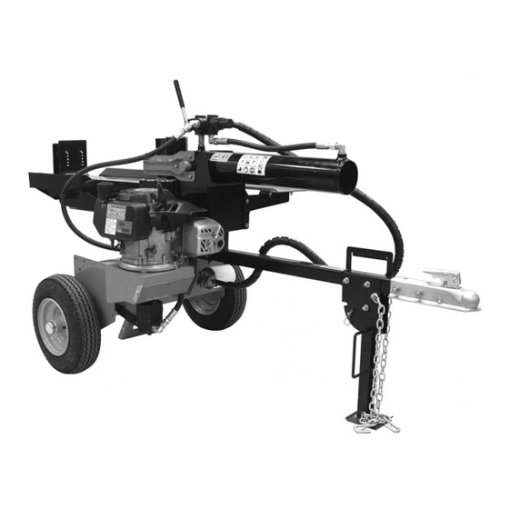
IDENTIFICATION
1. Draw Bar
2. 1/2 x 1" Hex Bolt (4)
3. 1/2" Hex Nut (4)
4. P-Clamp
5. Safety Chain
6. Front Stand
7. Front Stand Lock Pin
8. Hydraulic Cylinder
9. Control Lever
10. Splitter Wedge
11. Beam
12. Rear Stabilizer
13. Stripper Plate
14. Beam Lock
15. Clevis Pin
16. Cotter Pin
17. Control Valve
18. ISO 32 Hydraulic Fluid (part # 00069100) – Not Included
19. 3/8 x 1" Hex Bolt (1)
20. 3/8" Hex Nut (1)
© Copyright 2013 Ariens Company
10
13
12
Log Splitter
Setup Instructions
Instructions Pour La Mise En Place
Instrucciones Para Su Montaje
9
17
14
1
7
6
Tools Required:
EN - 1
16
15
8
4
19
5
2
• Two 3/4" wrenches or sockets
• Two 9/16" wrenches or sockets
• One 1/2" wrench or socket
• One 3/8" wrench or socket
• Thin-nosed pliers
• Wire cutters
02/13
18
Not
Included
20
3
04582200A
Publicidad

Resumen de contenidos para Ariens Gravely
- Página 1 • One 3/8" wrench or socket 18. ISO 32 Hydraulic Fluid (part # 00069100) – Not Included • Thin-nosed pliers 19. 3/8 x 1" Hex Bolt (1) • Wire cutters 20. 3/8" Hex Nut (1) 02/13 04582200A © Copyright 2013 Ariens Company EN - 1...
- Página 2 ASSEMBLY WARNING: AVOID INJURY. Read and understand the entire Safety section in the Support draw bar (# 1). Remove and dispose of four 1/4 x Owner’s Manual before proceeding. 1/2" Taptite bolts retaining draw bar to frame. DO NOT start engine until instructed and all Remove and assembly steps have been completed.
- Página 3 Ensure that beam lock (# 14) is seated in hole and rotate Remove hair pin, washer, and clevis pin retaining beam (# 11) into horizontal position until it locks into wedge (# 10) to hydraulic cylinder. Retain for position. Lock must engages fully. assembly.
- Página 4 Slide wedge back to cylinder and reinstall clevis pin, Attach hydraulic hose to draw bar using P-clamp washer and hair pin. (# 4), 3/8 x 1" hex bolt (# 19) and hex nut (# 20). Roll unit off of crate bottom. Install clevis pin, washer and hair pin.
- Página 5 Fendeuse à bois Instructions pour la mise en place Inclus IDENTIFICATION 1. Barre de remorquage 2. Boulon hexagonal de 1/2 x1" (4) 3. Écrou hexagonal 1/2" (4) 4. Attache P 5. Chaîne de sécurité 6. Béquille avant 7. Goupille de verrouillage béquille avant 8.
- Página 6 MONTAGE AVERTISSEMENT : POUR ÉVITER DE SE BLESSER. Lire et comprendre Soutenir la barre de remorquage (# 1). Desserrer et toute la section Sécurité du manuel retirer les éléments de fixation qui fixent la barre de du propriétaire avant de poursuivre. remorquage au châssis.
- Página 7 Veiller à ce que le verrou de poutre (# 14) se trouve dans Retirer la goupille, la rondelle et l’axe de chape le trou et tourner la poutre (# 11) en position horizontale qui retiennent le coin de fendage (# 10) sur jusqu’à...
- Página 8 Refaire glisser le coin de fendage dans le cylindre et Fixer le tuyau hydraulique à la barre d’attelage remonter l’axe de chape, la rondelle et la goupille. à l’aide d’une attache P (# 4), d’un boulon hexagonal de 3/8 x 1" (# 19) et d’un écrou Poser l’axe de chape, la rondelle et la goupille.
-
Página 9: Partidora De Troncos
Partidora de troncos Instrucciones para su montaje incluido IDENTIFICACIÓN 1. Barra de tiro 2. Perno hexagonal de 1/2 x 1" (1,3 x 2,5 cm) (4) 3. Tuerca hexagonal de 1/2" (1,3 cm) (4) 4. Brida P 5. Cadena de seguridad 6. -
Página 10: Montaje
MONTAJE ADVERTENCIA: EVITE LAS LESIONES. Antes de proceder, lea atentamente toda la Sujete la barra de tiro (# 1). Afloje y retire las sujeciones sección de Seguridad del Manual del usuario. que sujetan la barra de tiro al bastidor. NO arranque el motor hasta que no se le pida y hayan finalizado todas las operaciones Retirar y desechar. - Página 11 Asegúrese de que el bloqueo de la viga (# 14) se sitúe Quite la horquilla, la arandela y el pasador en el orificio y gire la viga (# 11) en posición horizontal de horquilla que sujetan la cuña (# 10) al cilindro hasta que se bloquee en posición.
- Página 12 Mueva de nuevo la cuña hacia el cilindro y monte Conecte la manguera hidráulica a la barra el pasador de horquilla, la arandela y la horquilla. de tiro con la brida P (# 4), el perno hexagonal de 3/8 x 1" (1,0 x 2,5 cm) (# 19) y la tuerca Montar pasador de horquilla, arandela y horquilla.