Publicidad
Idiomas disponibles
Idiomas disponibles
Enlaces rápidos
EN DE FR ES
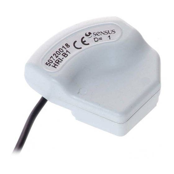
INSTALLATION AND OPERATING INSTRUCTIONS – HRI
HRI is available in two versions.
• The HRI-A PulseUnit provides high-resolution
pulse outputs.
• The HRI-B DataUnit has additionally a data
interface for reading meter ID number and
index.
Delivery parts 1
HRI sensor, bayonet ring, cut meter lid, 2 screws,
2 screw seals, 1 adhesive seal
Installation:
Just before mounting the HRI on the meter it
is essential to remove the aluminium foil at the
bottom side. A screwdriver Torx (T8) or slot
(3.5*0.6) is recommended for mounting. The
torque should be 0.6 Nm
Meters with plastic register 2
Change the lids and put the HRI on the meter, so
that the two pins on top of the register fit exactly
into the holes at the bottom of the HRI. Fit the two
screws. For tamper protection fit the plastic seals
on top of the screws. The bayonet ring and the
adhesive seal are not used for this register type.
Meter with glass-copper register 3
First exchange the lids. Mount the HRI with both
the screws on the bayonet ring. For tamper
protection fit the plastic seals on the top of the
screws. Fit the bayonet ring with the mounted
HRI on the top of the meter register and turn
it until it is drops into place. Push and turn the
bayonet ring clockwise until the lever clicks into
place. If required fit the adhesive seal. To remove
the HRI lift the lever and rotate anticlockwise.
Type 4
Depending on the order specification, HRI can be
in these different pulse modes:
HRI Pulse Unit: Type A3 and A4
HRI Data Unit: Type B2, B3 and B4
with following pulse weights:
Possible values for residential meters:
D = 1 / 2.5 / 5 / 10 / 25 / 50 / 100 / 250 / 500 or 1000
Wire
Pulse
mode
l1 (white)
Tamper/ Error
B1
Balanced pulses**
"normally open"
Forward flow
Reverse flow
B2
pulses
pulses
Forward and
A3/B3
Flow direction
backwards pulses
Tamper/ Error
A4/B4
Balanced pulses**
"normally closed"
**) Balanced pulses: Reverse flow must be
compensated by identical forward flow before
more pulses are output. That means, no output
pulses during this period even the meter is
counting forward.
Ground (brown)
DATA (green) only for HRI Type B (alternatively
for external power supply)
Battery or external power supply (for all B types):
3V Lithium battery with autonomy lifetime of
more than 10 years.
With unbroken permanent external power supply
of 24VDC (max. 50VDC) unit lifetime is increased
to more than 15 years. In case of external power
failure the battery of the module takes over the
supply. All stored data are retained and the
volume detection continues automatically. The
external power supply can also be an M-Bus
central unit.
www.sensus.com
info.int@xyleminc.com
Technical data
• Temperature range
Storage: -20 °C to +65 °C
Operation: -10 °C to +65 °C
• Cable length: 1.5 m
• Hermetically sealed housing IP 68
• EMC acc. EEC directive 98/34 equal European
standards EN61000-6-1
Pulse-outputs (I1/I2) all types
Open drain transistor switch according ISO/TC30
Vmax: 24V DC / Imax: 20mA / Pmax: 0,48VA /
fmax: 5Hz
Max. voltage by closed switch: 0.3V + I * 260 Ω
If the data interface isn't used the serial resistance
can be reduced by 150 Ω with the connection of
green and brown wire.
Meter
HRI-A
DN
A4
15-40
A3
15-40
HRI-B: Pulse length 124 ms fixed,
Flow direction (A3/B3) signal l2 is 18μs prior to I1
Operational cable length up to 10 m
Transient
voltage
recommended for wiring outside buildings.
Data interface (HRI-Bx only)
M-Bus and MiniBus (Auto speed detection:
300/2400 Baud)
Protocol according EN13757-3 equal IEC 870 / EN
1434-3
Data: meter ID, meter index (optional 1 litre or 1
m3 resolution)
Operational cable length: according to M-Bus
specification.
With M-Bus reading is unlimited, with MiniBus
the reading shouldn't be more than 5 times per
day to avoid a battery lifetime of less than 10
years.
With the data interface the following values
can be set via MiniCom (version >3.0); standard
setting from the factory in brackets:
• Primary address (0)
• Secondary address (HRI-Fabrication No.)
l2 (yellow)
• Meter ID No. (HRI-Fabrication No.)
• Meter index (0); if the aluminium foil is
missing, index can be different
• Pulse mode (according the order)
• Pulse weight (according the order)
Attention: The resolution of meter index can't be
changed, so this setting must be correctly defined
with the order.
If the HRI is ordered mounted on top of a meter,
the secondary address, meter ID no. and meter
index are preset with the meter's values. Setting
on site isn't necessary.
If data interface and pulse output is used at the
same time, potential free connection for the
connected devices are requested. During data
communication pulse lost is possible depending
on the pulse collector's input circuit.
Disposal instructions
This product contains a lithium
battery. To protect the environment
it should not be disposed in
household
rubbish
serviceable life is over. Disposal
can take place through a Sensus
Service Center. If however you
want to take care of the disposal yourself, please
comply with the local and national regulations for
environmental protection.
Pulse weight (length)
D1
D10
D100
(124ms)
(500ms)
(500ms)
1l
10l
100l
1l
----
----
protection
is
highly
when
its
1
2
4
1
3
2
3
4
0.3 V
Application examples
All connections with external power supply are optional.
It can use the HRI's internal battery.
Flow
forward
meter index
backwarts
Mode A4, B1, B4
l1 (balanced)
open
close
Mode B2
l1 (forward)
open
close
l2 (backwards)
open
close
Mode A3 / B3
l1 (forward & backwards)
open
close
l2 (direction)
open
forward
close
backwards
green
PLC with switched
HRI
ground
A4
HRI with external
B4
white
power supply
brown
green
PLC with
white
switched
HRI
1kΩ
brown
power
A4
supply
B4
TR100 (829372)
forward
white
Remote display
count 20 HZ
HRI
This application can
(B2)
yellow
be also used as a
count 20 HZ
test tool for all HRI
types
brown
brown
yellow
HRI
Connection with
white
(A3)
CDL
HRI
6
5
l1 white or
l2 yellow
Ground: brown
Data: green (HRI-B)
forward
+24 V
pulse
unit
PLC
+24V
forward
0V
88888888
backwards
0V
88888888
only with A2/B2
soldering side
plug
Publicidad

Resumen de contenidos para Xylem SENSUS HRI-A
- Página 1 EN DE FR ES INSTALLATION AND OPERATING INSTRUCTIONS – HRI HRI is available in two versions. Technical data • The HRI-A PulseUnit provides high-resolution • Temperature range pulse outputs. Storage: -20 °C to +65 °C • The HRI-B DataUnit has additionally a data Operation: -10 °C to +65 °C interface for reading meter ID number and •...
- Página 2 EN DE FR ES EINBAU- UND BETRIEBSANWEISUNG - HRI Der HRI ist in zwei Ausführungen erhältlich: Zentrale erfolgen. • HRI-A PulseUnit, hochauflösender Technische Daten Impulsgeber unter Berücksichtigung • Umgebungstemperaturen Fließrichtung Lagerung: -20 °C ... +65 °C • HRI-B DataUnit, wie HRI PulseUnit aber mit Betrieb: -10 °C ...
-
Página 3: Declaration Of Conformity • Konformitätserklärung
EN DE FR ES Declaration Of Conformity • Konformitätserklärung www.sensus.com info.int@xyleminc.com... - Página 4 EN DE FR ES MANUEL HRI Le HRI est disponible en deux versions : Caractéristiques techniques • HRI-A PulseUnit : fournit des impulsions hautes • Plage de température résolution. Stockage : -20 °C to +65 °C • HRI-B DataUnit équipé en plus d’une sortie Utilisation : -10 °C to +65 °C interface données...
- Página 5 EN DE FR ES MANUAL HRI El HRI está disponible en dos versiones. externa puede ser suministrada por el máster • El HRI-A PulseUnit proporciona una salida de M-Bus. pulsos de alta resolución. Datos Técnicos • El HRI-B DataUnit tiene una salida adicional •...
- Página 6 EN DE FR ES Déclaration de conformité • Declaración de conformidad www.sensus.com info.int@xyleminc.com...