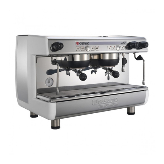
Resumen de contenidos para Casadio undici
- Página 1 MANUALE DEL TECNICO ENGINEER'S MANUAL MANUEL DU TECHNICIEN TECHNIKERHANDBUCH MANUAL DEL TÉCNICO MANUAL DO TÉCNICO (rev. 1736)
- Página 3 Indice - Index - Index - Inhaltsverzeichnis - Indice - Indice Pag. - Page Page - Seite Pag. - Pag. Smontaggio - Disassembly - Demontage Abmontierung - Desmontaje - Desmontagem Smontaggio fiancate - Removal of the side panels Démontage des côtés - Abnahme der Seitenpaneele Desmontaje paneles laterales - Desmontagem lados Pannello frontale inox - Stainless steel front panel Panneau frontal inox - Abnahme des vorderen Paneels aus Edelstahl...
- Página 4 Smontaggio - Disassembly - Demontage - Abmontierung - Desmontaje - Desmontage FIANCATE Allentare le viti di fissaggio (A) e rimuovere la fiancata (L). SIDES Loosen the screws (A) and remove side panel (L). COTES Dévisser les vis (A) et enlever le flanc (L). SEITENWÄNDE Lösen Sie die Schrauben (A) und nehmen Sie das Seitenteil ab (L).
- Página 5 PANNELLO POSTERIORE Lo smontaggio del pannello posteriore deve essere eseguito solo dopo aver rimosso lo scaldatazze. Svitare le (n° ) viti di fissaggio (D) e rimuovere il pannello. BACK PANEL The back panel may be removed only after the cup warmer has been removed.
- Página 6 Regolazioni - Setting - Reglages - Einstellungen - Regulaciones - Regulações PRESSOSTATO A - Vite di regolazione pressione caldaia PRESSURESTAT A - Screw for adjusting the boiler pressure PRESSOSTAT A - Vis de réglage pression chaudière DRUCKS CHALTER A - Kesseldruck-Einstellschraube PRESSOSTATO A - Tornillo regulación presión caldera PRESSOSTATO...
- Página 7 MACCHINE - MACHINES CN10 MACHINES - MASCHINEN Dip 1 Dip 2 Dip 3 Dip 4 Dip 5 Dip 6 Dip 7 Dip 8 CN14 CN11 MÁQUINAS - MÁQUINAS (n.d.) 1, 2, 3 gr. DICI (n.d.) SI/YES OFF ON CN10 CN11 Dip 1÷8 4°...
- Página 8 CN10/CN11 “ON” ponticello presente (elettrovalvole 220V) CN10/CN11 “ON” bridge present (solenoid valve 220V) CN14 ON, solo per alcuni modelli CN14 ON, only for certain models Dip1 ON, inserimento dati standard (¹) Dip1 ON, input of standard data (¹) (¹) Al termine delle operazioni di inserimento (¹) Upon completion of the standard data dati standard, riportare il DIP 1 sulla posizione input operations, position DIP 1 to OFF again.
- Página 9 Schema elettrico - Wiring diagram - Schéma éléctrique - Elektrischer Schaltplan - Esquema electrico - Esquema eléctrico Pressure sensor Service boiler resistance Fase R Main switch Power switch Neutro N NT2A NT2B Boiler security thermostat POWER CPU board CPU-CN1 AMP350777-1_2P 350777-1 MONOFASE: POWER -...
- Página 10 Pressure sensor SERVICE BOILER RESISTENCE 532.136.900 532.136.900 532.136.900 532.136.900 532.136.900 532.136.900 532.136.900 532.136.900 TT1D NN1C Main switch Power switch Boiler security thermostat TT1B TT1C TT1D NN1B NN1C NN1A TT1A POWER TRIFASE CPU board POWER CPU-CN1 AMP350777-1_2P 350777-1 DATA DISEGNATO CONTROLLATO DIS.
- Página 11 NEUTRO CPU-CN5 3G - 2G FASTON_63_F 532.137.200 CPU Board RLV1 BASSA TENSIONE AMPMODU2_2P 280358 Gr 3 (SX) 532.137.000 280362 280362 280362 AMPMODU2_10P AMPMODU2_10P AMPMODU2_10P 9 10 CGRID90142_10P 90142-0010 DV3_ CN7-1_2_3 CPU-CN8 CN7-CPU CPU-CN9 AMPMODU2_4P 280359 Gr 2 (SX) CN3-4 CN13-CPU CN12-CPU CPU_CN3 CONNETTORE_EV...
- Página 12 COLLEGAMENTO SCALDA TAZZE. - ST - IG - ST - LS1_c0 NERO ROSSO ROSSO FASTON_63_F FASTON_63_F PIGYBACK_63 532.137.200 532.137.200 532.138.900 NS1_c0 ROSSO AMP350766-1_3P NERO ROSSO FASTON_63_F FASTON_63_F 350766-1 532.137.200 PIGYBACK_63 532.137.200 532.138.900...
- Página 13 CN12 7 CN12 8 CN12 3 CN12 4 CN12 8 CN12 9 CN12 10 CN12 5 CN12 6 CN12 9 100nF CN12 10 47 Ohm FUNZIONALE UNDICI Compatta DATE DRAWING BY CHECKED BY APROVED BY . .1 IF(ELLCAD) CONTRI ERBA...
- Página 14 Circuito idraulico - Hydraulic circuit - Circuit hydraulique - Hydraulikplan - Circuito hidraulico - Circuito hidraulico In 2,5 mm 3,5 mm 0,8 mm 1524...
- Página 15 Circuito idraulico - Hydraulic circuit - Circuit hydraulique - Hydraulikplan - Circuito hidraulico - Circuito hidraulico In 2,5 mm 3,5 mm 0,8 mm 1524...
- Página 16 Circuito idraulico - Hydraulic circuit - Circuit hydraulique - Hydraulikplan - Circuito hidraulico - Circuito hidraulico In 2,5 mm 3,5 mm 0,8 mm A COMPACT 1608...
- Página 17 Legenda - Legend - Legende - Legende - Leyenda - Legenda LEGENDA LEGEND LEGENDE = Lancia erogazione vapore = Steam dispensing nozzle = Lance débit vapeur = Lancia erogazione acqua calda = Hot water dispensing nozzle = Lance débit eau chaude 14 = Manometro caldaia/pompa 14 = Boiler/pump pressure gauge 14 = Manomètre chaudière/pompe...


