Tabla de contenido
Publicidad
Idiomas disponibles
Idiomas disponibles
Enlaces rápidos
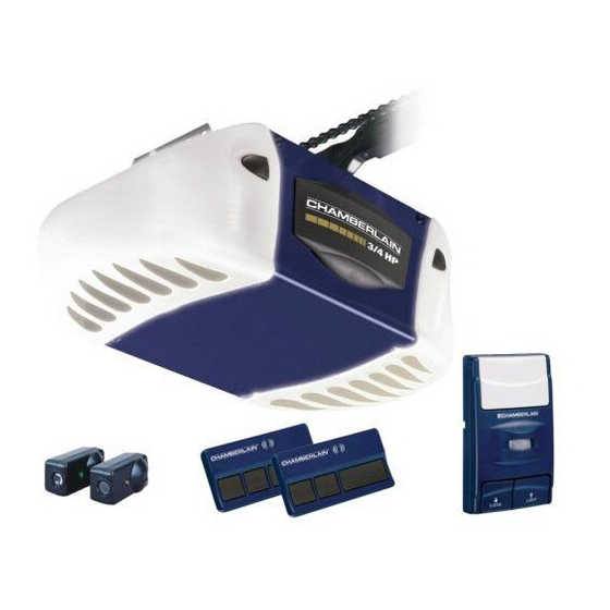
GARAGE DOOR OPENER
Models PD752DS 3/4 HP
For Residential Use Only
Owner's Manual
Please read this manual and the enclosed safety materials carefully!
■
Fasten the manual near the garage door after installation.
■
The door WILL NOT CLOSE unless The Protector System
■
and properly aligned.
Periodic checks of the opener are required to ensure safe operation.
■
The model number label is located on the left side panel of your opener.
■
®
PD752KLDS 3/4 HP
The Chamberlain Group, Inc.
845 Larch Avenue
Elmhurst, Illinois 60126-1196
www.chamberlain.com
®
is connected
Publicidad
Capítulos
Tabla de contenido

Manuales relacionados para Chamberlain POWER DRIVE SECURITY+ PD752DS 3/4 HP


Resumen de contenidos para Chamberlain POWER DRIVE SECURITY+ PD752DS 3/4 HP
- Página 1 The Chamberlain Group, Inc. 845 Larch Avenue Elmhurst, Illinois 60126-1196 www.chamberlain.com ® GARAGE DOOR OPENER Models PD752DS 3/4 HP PD752KLDS 3/4 HP For Residential Use Only Owner’s Manual Please read this manual and the enclosed safety materials carefully! ■ Fasten the manual near the garage door after installation.
-
Página 2: Tabla De Contenido
TABLE OF CONTENTS Introduction Adjustment 27-29 Safety symbol and signal word review ....... 2 Adjust the travel limits ..........27 Preparing your garage door ........3 Adjust the force ............28 Tools needed .............. 3 Test the safety reversal system ....... 29 Planning .............. -
Página 3: Preparing Your Garage Door
Preparing your garage door Before you begin: To prevent possible SERIOUS INJURY or DEATH: • Disable locks. • ALWAYS call a trained door systems technician if • Remove any ropes connected to garage door. garage door binds, sticks, or is out of balance. An unbalanced garage door may not reverse when •... -
Página 4: Planning
Planning • Do you have an access door in addition to the Identify the type and height of your garage door. garage door? If not, Model 7702CB Emergency Survey your garage area to see if any of the Key Release is required. See Accessories page. conditions below apply to your installation. -
Página 5: One-Piece Door Installations
Planning (Continued) ONE-PIECE DOOR INSTALLATIONS Without a properly working safety reversal system, persons (particularly small children) could be • Generally, a one-piece door does not require SERIOUSLY INJURED or KILLED by a closing garage reinforcement. If your door is lightweight, refer to door. -
Página 6: Carton Inventory
Carton Inventory Your garage door opener is packaged in one carton FOAM. Hardware for assembly and installation is which contains the motor unit and all parts illustrated shown on the next page. Save the carton and below. Accessories will depend on the model packing material until installation and adjustment is purchased. -
Página 7: Hardware Inventory
Hardware Inventory Separate all hardware and group as shown below for the assembly and installation procedures. ASSEMBLY HARDWARE Bolt 1/4"-20x1-3/4 (1) Lock Washer 3/8" (1) 3/8" (1) Bolt 1/4"-20x2-1/2 (1) Lock Nut 1/4"-20 (2) Idler Bolt (1) Master Link (2) Trolley Threaded Shaft (1) INSTALLATION HARDWARE Spacer (2) -
Página 8: Assembly Step
ASSEMBLY STEP 1 Assemble the Rail & Install the To prevent INJURY from pinching, keep hands and Trolley fingers away from the joints while assembling the rail. To avoid installation difficulties, do not run the garage door opener until instructed to do so. The front rail has a cut out “window”... -
Página 9: Fasten The Rail To The Motor Unit And
ASSEMBLY STEP 2 Fasten the Rail to the Motor Unit To avoid SERIOUS damage to garage door opener, use ONLY those bolts/fasteners mounted in the top of • Insert a 1/4"-20x2-1/2 bolt, washer and spacer into the opener. the cover protection bolt hole on the back end of the rail as shown. -
Página 10: Install The Chain/Cable
ASSEMBLY STEP 4 Install the Chain/Cable To avoid possible SERIOUS INJURY to fingers from moving garage door opener: 1. Pull the cable around the idler pulley and toward the trolley. • ALWAYS keep hand clear of sprocket while operating opener. 2. -
Página 11: Tighten The Chain
ASSEMBLY STEP 5 Figure 1 Trolley Tighten the Chain Lock Outer Threaded Washer Shaft To Tighten Outer Nut • Spin the inner nut and lock washer down the trolley threaded shaft, away from the trolley. • To tighten the chain, turn outer nut in the direction Inner Nut shown (Figure 1). -
Página 12: Installation Step
INSTALLATION STEP 1 Unfinished Determine the Header Bracket Ceiling OPTIONAL Location CEILING MOUNT HEADER BRACKET Header Wall To prevent possible SERIOUS INJURY or DEATH: Vertical Centerline of Garage Door • Header bracket MUST be RIGIDLY fastened to structural support on header wall or ceiling, otherwise Structural garage door might not reverse when required. -
Página 13: Install The Header Bracket
INSTALLATION STEP 2 Wall Mount Install the Header Bracket You can attach the header bracket either to the wall above the garage door, or to the ceiling. Follow the instructions which will work best for your particular requirements. Do not install the header bracket over drywall. -
Página 14: Attach The Rail To The Header Bracket
INSTALLATION STEP 3 Attach the Rail to the Header Bracket NOTE: (Optional) With some existing installations, you may re-use the old header bracket with the two plastic spacers included in the hardware bag. Place the spacers inside the bracket on each side of the rail, as illustrated. -
Página 15: Position The Opener
INSTALLATION STEP 4 Position the Opener To prevent damage to garage door, rest garage door Follow instructions which apply to your door type as opener rail on 2x4 placed on top section of door. illustrated. SECTIONAL DOOR OR ONE-PIECE DOOR WITH TRACK A 2x4 laid flat is convenient for setting an ideal door-to-rail distance. -
Página 16: Hang The Opener
INSTALLATION STEP 5 Hang the Opener To avoid possible SERIOUS INJURY from a falling garage door opener, fasten it SECURELY to structural Three representative installations are shown. Yours supports of the garage. Concrete anchors MUST be used may be different. Hanging brackets should be angled if installing ANY brackets into masonry. -
Página 17: Install The Door Control
INSTALLATION STEP 6 Install the Door Control To prevent possible SERIOUS INJURY or DEATH from electrocution: Locate door control within sight of the door at a minimum height of 5 feet (1.5 m) where small children • Be sure power is not connected BEFORE installing door cannot reach, and away from moving parts of the door control. -
Página 18: Install The Lights
INSTALLATION STEP 7 Install the Lights To prevent possible OVERHEATING of the endpanel or light socket: • Install a 100 watt maximum light bulb in each • DO NOT use short neck or specialty light bulbs. socket. Light bulb size should be A19, standard neck only. -
Página 19: Electrical Requirements
INSTALLATION STEP 9 Electrical Requirements To prevent possible SERIOUS INJURY or DEATH from electrocution or fire: To avoid installation difficulties, do not run the opener at this time. • Be sure power is not connected to the opener, and disconnect power to circuit BEFORE removing cover to To reduce the risk of electric shock, your garage establish permanent wiring connection. -
Página 20: Install The Protector System
INSTALLATION STEP 10 Install The Protector System ® Be sure power is not connected to the garage door opener BEFORE installing the safety reversing sensor. The safety reversing sensor must be connected and aligned correctly before the garage door To prevent SERIOUS INJURY or DEATH from a closing opener will move in the down direction. -
Página 21: Installing The Brackets
INSTALLING THE BRACKETS Figure 1 DOOR TRACK MOUNT (RIGHT SIDE) Be sure power to the opener is disconnected. Install and align the brackets so the sensors will face Door each other across the garage door, with the beam no Track higher than 6"... -
Página 22: Mounting And Wiring The Safety Reversing Sensors
MOUNTING AND WIRING THE SAFETY Figure 5 REVERSING SENSORS Wing Nut 1/4"-20 • Slide a 1/4"-20x1/2" carriage bolt head into the slot on each sensor. Use wing nuts to fasten sensors to brackets, with lenses pointing toward each other across the door. Be sure the lens is not obstructed Carriage Bolt by a bracket extension (Figure 5). -
Página 23: Fasten The Door Bracket
INSTALLATION STEP 11 Fasten the Door Bracket Fiberglass, aluminum or lightweight steel garage doors WILL REQUIRE reinforcement BEFORE installation of Follow instructions which apply to your door type door bracket. Contact your door manufacturer for as illustrated below or on the following page. reinforcement kit. -
Página 24: One-Piece Doors
ONE-PIECE DOORS Please read and comply with the warnings and reinforcement instructions on the previous page. They apply to one-piece doors also. • Center the door bracket on the top of the door, in line with the header bracket as shown. Mark either the left and right, or the top and bottom holes. -
Página 25: Connect Door Arm To Trolley
INSTALLATION STEP 12 Pulley Connect Door Arm to Trolley Follow instructions which apply to your door type as illustrated below and on the following page. Trolley Outer Stop Bolt Inner SECTIONAL DOORS ONLY Trolley Trolley Ring • Make sure garage door is fully closed. Pull the Clevis Pin Fastener 5/16"x1"... -
Página 26: All One-Piece Doors
ALL ONE-PIECE DOORS Door Bracket Ring 1. Assemble the door arm, Figure 4: Fastener Nuts Lock • Fasten the straight and curved door arm sections 5/16"-18 Washers together to the longest possible length (with a 2 5/16" Clevis Pin or 3 hole overlap). Straight 5/16"x1-1/4"... -
Página 27: Adjustment
ADJUSTMENT STEP 1 Adjust the UP and DOWN Travel Limits Without a properly installed safety reversal system, persons (particularly small children) could be Limit adjustment settings regulate the points at which SERIOUSLY INJURED or KILLED by a closing garage door. the door will stop when moving up or down. -
Página 28: Adjust The Force
ADJUSTMENT STEP 2 Adjust the Force Without a properly installed safety reversal system, Force adjustment controls are located on the right persons (particularly small children) could be panel of the motor unit. Force adjustment settings SERIOUSLY INJURED or KILLED by a closing garage regulate the amount of power required to open and door. -
Página 29: Test The Safety Reversal System
ADJUSTMENT STEP 3 Test the Safety Reversal System Without a properly installed safety reversal system, persons (particularly small children) could be TEST SERIOUSLY INJURED or KILLED by a closing garage • With the door fully open, place a 1-1/2" (3.8 cm) door. -
Página 30: Operation
WARNING OPERATION IMPORTANT SAFETY INSTRUCTIONS WARNING WARNING To reduce the risk of SEVERE INJURY or DEATH: 1. READ AND FOLLOW ALL WARNINGS AND 9. If one control (force or travel limits) is adjusted, the INSTRUCTIONS. other control may also need adjustment. 2. -
Página 31: Using The Wall-Mounted Door Control
Using the Wall-Mounted Additional feature when used with the 3-Button hand-held remote Door Control To control the opener lights: MOTION DETECTING DOOR CONTROL In addition to operating the door, Press the push bar to open or you may program the remote to Push close the door. -
Página 32: Care Of Your Opener
THE REMOTE CONTROL BATTERY CARE OF YOUR OPENER LIMIT AND FORCE ADJUSTMENTS: Weather conditions may FORCE CONTROLS cause some minor changes To prevent possible SERIOUS INJURY or DEATH: in door operation requiring • NEVER allow small children near batteries. some re-adjustments, •... -
Página 33: Having A Problem
HAVING A PROBLEM? 1. My door will not close and the light bulbs blink on my motor unit: The safety reversing sensor Bell Wire must be connected and aligned correctly before the garage door opener will move in the down direction. •... -
Página 34: Diagnostic Chart
Bell Wire Diagnostics Installed Located On Safety Reversing Motor Unit Sensor LED or Your garage door opener is programmed with Diagnostic self-diagnostic capabilities. The “Learn” button/diagnostic "Learn" LED will flash a number of times then pause signifying it has Safety Reversing Sensor Button found a potential issue. -
Página 35: Programming
PROGRAMMING NOTICE: If this Security✚ ® garage door opener is operated with a non-rolling code transmitter, the technical measure in the receiver of the garage door opener, which provides security against code-theft devices, will be circumvented. The owner of the copyright in the garage door opener does not authorize the purchaser or supplier of the non-rolling code transmitter to circumvent that technical measure. -
Página 36: To Add, Reprogram Or Change A Keyless Entry Pin
To Add, Reprogram or Change a Keyless Entry PIN NOTE: Your new Keyless Entry must be programmed to operate your garage door opener. USING THE “LEARN” BUTTON USING THE MOTION DETECTING DOOR CONTROL NOTE: This method requires two people if the Keyless 1. -
Página 37: Repair Parts
REPAIR PARTS Rail Assembly Parts PART DESCRIPTION 4A1008 Master link kit 41C5141-1 Complete trolley assembly 41A5665-2 Complete rail 144C56 Idler pulley 41A5807-3 Chain and cable 12D598-1 “U” bracket NOT SHOWN 183A163 Wear pads Installation Parts KEY PART DESCRIPTION 41C472-5 Motion detecting door control panel 953D 3-Button remote control 10A20... -
Página 38: Motor Unit Assembly Parts
Motor Unit Assembly Parts (Down) LIMIT SWITCH Brown Contact ASSEMBLY Wire Grey Wire Drive Gear Center Limit (Up) Yellow Contact Contact Wire PART PART DESCRIPTION DESCRIPTION 41A5615 Chain Spreader 41A5633-2 Cover 41A5585 Gear and sprocket assembly. 41A2818 Limit switch drive & retainer Complete with: Spring washer, 41D3452-2 Limit switch assembly... -
Página 39: Accessories
5 opener remote or from anywhere in minutes when it detects a person their home with an additional entering the garage. Sensor can Chamberlain Security✚ remote. ® be easily deactivated when desired. CLDM1... -
Página 40: How To Order Repair Parts
LIFETIME MOTOR LIMITED WARRANTY The Chamberlain Group, Inc. (“Seller”) warrants to the first retail purchaser of this product, for the residence in which this product is originally installed, that it is free from defect in materials and/or workmanship for a period of one year from the date of purchase [and that the motor is free from defect in materials and/or workmanship for the lifetime of the product]. - Página 41 The Chamberlain Group, Inc. 845 Larch Avenue Elmhurst, Illinois 60126-1196 www.chamberlain.com ® ABRE-PUERTAS DE GARAJE Modelos PD752DS 3/4 HP PD752KLDS 3/4 HP Sólo para uso residencial Manual Del Usuario ¡Lea atentamente el contenido de este manual y las instrucciones de seguridad en ■...
- Página 42 CONTENIDO Introducción Ajustes 27-29 Revisión de los símbolos y términos de seguridad ....2 Ajuste del límite del recorrido ..........27 Preparación de la puerta del garaje ........3 Ajuste de la fuerza ............. 28 Herramientas necesarias ............. 3 Prueba del sistema de reversa de seguridad ....29 Planificación ..............4-5 Prueba del Protector System ®...
-
Página 43: Preparación De La Puerta Del Garaje
Preparación de la puerta del garaje ADVERTENCIA ADVERTENCIA Antes de comenzar: Para evitar la posibilidad de LESIONES GRAVES O INCLUSO • Desactive las trabas y seguros. LA MUERTE: • Quite toda cuerda conectada a la puerta del garaje. • Si la puerta se atora, se atasca o está desbalanceada, SIEMPRE llame a un técnico profesional para que la repare. -
Página 44: Planificación
Planificación • ¿Hay otra puerta de acceso además de la puerta del Identifique la altura y el tipo de puerta de garaje que tiene. garaje? Si no es así, será necesario contar con el Revise el área de su garaje y observe si alguna de las Desenganchador externo rápido, Modelo 7702CB. -
Página 45: Instalaciones De Puertas De Una Pieza
Planificación (continuación) ADVERTENCIA ADVERTENCIA INSTALACIONES DE PUERTAS DE UNA PIEZA Si el sistema de auto-reversa de seguridad no se ha instalado debidamente, las personas (y los niños pequeños en • Por lo general, una puerta de una pieza no necesita particular) podrían sufrir LESIONES GRAVES O INCLUSO LA refuerzo. -
Página 46: Inventario De La Caja De Cartón
Inventario de la caja de carton Su abre-puertas viene empacado en una caja de cartón QUE PODRÍAN QUEDAR PIEZAS ATRAPADAS EN LA que contienen el motor y todas las piezas que se muestran ESPUMA SINTÉTICA. Toda los accesorios de fijación para en la siguiente ilustración. -
Página 47: Inventario De Piezas
Inventario de piezas Antes de la instalación, organice todas las piezas en grupos como se muestra en la siguiente ilustración. PERNERÍA DE ENSAMBLE Arandela de Tuerca de 3/8 de pulg. (1) Perno de 1/4-20x1-3/4 de pulg. (2) presión de 3/8 de pulg. (1) Perno de 1/4-20x2-1/2 de pulg. -
Página 48: Montaje, Paso
MONTAJE, PASO 1 PRECAUCIÓN PRECAUCIÓN Monte el riel y instale el trole Para evitar QUE SE PELLIZQUE, conserve los manos y dedos No encienda ni use el abre-puertas hasta que llegue al lejos de las juntas cuando monte el reil. paso de la instalación correspondiente, de otra manera corre el riesgo de complicar el proceso de instalación. -
Página 49: Ensamblado
ENSAMBLADO PASO 2 PRECAUCIÓN PRECAUCIÓN Fijación del riel al motor Para prevenir una SERIA avería al abre-puertas, utilice SÓLO • Introduzca un tornillo de 1/4-20 x 2-1/2 de pulg., con los pernos y accesorios montados sobre el abre-puertas. arandela y separador, en el agujero del perno de protección de la tapa ubicado en la parte trasera del riel (tal como se muestra). -
Página 50: Instalación De La Cadena/Cable
ENSAMBLADO PASO 4 ADVERTENCIA ADVERTENCIA Instalación de la cadena/cable Para evitar posibles LESIONES GRAVES en los dedos causadas 1. Pase el cable por la polea guía y haci el carro. por las partes móviles del abre-puertas de garaje: 2. Conecte el cable al orificio extendido de retención en el •... -
Página 51: Ajuste De La Cadena
ENSAMBLADO PASO 5 Ajuste de la cadena Figura 1 • Gire la tuerca con su arandela por el eje roscado del Arandela Tuerca carro, en sentido opuesto al mismo. Eje roscado de presión externa del carro • Para ajustar la cadena, gire la tuerca externa en la Para ajustar la tuerca externa dirección indicada en la ilustración (Figura 1). -
Página 52: Instalación Paso
INSTALACIÓN PASO 1 Determinar la localización de soporte Cielo raso sin terminación MONTAJE de cabecera OPCIONAL DE MÉNSULA DE CABEZAL ADVERTENCIA ADVERTENCIA ADVERTENCIA EL TECHO 3.8 cm Pared de cabecera (2x4 pulg.) Para evitar una posible LESIÓN GRAVE O INCLUSO LA MUERTE: Línea vertical del ADVERTENCIA centro de la puerta... -
Página 53: Instalación De La Ménsula Del Cabezal
INSTALACIÓN PASO 2 Montaje en pared Instalación de la ménsula del cabezal La ménsula del cabezal se puede fijar a la pared sobre la puerta del garaje o en el cielo raso. Siga las instrucciones que sean más adecuadas para las necesidades de su instalación. -
Página 54: Colocación Del Riel En La Ménsula Del Cabezal
INSTALACIÓN PASO 3 Colocación del riel en la ménsula del cabezal NOTA: (Opcional) En ciertas instalaciones existentes, podría volver a utilizar la ménsula del sistema anterior con los dos separadores de plástico incluidos en la bolsa de accesorios. En tal caso, coloque los separadores en el interior de la ménsula a cada lado del riel, tal como se muestra en la ilustración. -
Página 55: Colocación Del Abre-Puertas
INSTALACIÓN PASO 4 PRECAUCIÓN PRECAUCIÓN Colocación del abre-puertas Para evitar que la puerta del garaje sufra daños, apoye el riel Siga las instrucciones correspondientes al tipo de puerta del abre-puertas sobre un tirante de madera de 3.8 cm de su garaje, como se muestra en la ilustración. (2x4 pulg.) colocado sobre la parte superior de la puerta. -
Página 56: Cuelgue El Abre-Puertas
INSTALACIÓN PASO 5 ADVERTENCIA ADVERTENCIA Cuelgue el abre-puertas Para evitar la posibilidad de una LESIÓN GRAVE si se cayera Se muestran tres instalaciónes representativas. Quizá su accidentalmente el abre-puertas, fíjelo FIRMEMENTE a instalación sea diferente. Las soportes colgantes se deben soportes estructurales del garaje. -
Página 57: Instalar El Control De La Puerta
ADVERTENCIA ADVERTENCIA INSTALACIÓN PASO 6 ADVERTENCIA ADVERTENCIA Instalar el control de la puerta Para evitar la posibilidad de una LESIÓN GRAVE O INCLUSO LA Ubique el control de la puerta de manera que quede a la MUERTE por electrocución: vista desde la puerta y a una altura mínima de 1.5 m •... -
Página 58: Instalación De La Bombilla
INSTALACIÓN PASO 7 PRECAUCIÓN PRECAUCIÓN Instalación de la bombilla Para evitar un posible SOBRECALENTAMIENTO del • Oprima las lengüetas de liberación a ambos lados de la portabombillas: lente. Rote la lente suavemente hacia atrás y hacia • NO utilice bombillas de cuello corto ni de tipo especial. abajo hasta que la bisagra quede en la posición •... -
Página 59: Requisitos Para La Instalación Eléctrica
INSTALACIÓN PASO 9 ADVERTENCIA ADVERTENCIA ADVERTENCIA Requisitos para la instalación eléctrica Para evitar la posibilidad de una LESIÓN GRAVE O INCLUSO Para evitar problemas con la instalación, no opere el LA MUERTE por electrocución o incendio: ADVERTENCIA abre-puertas de garaje ahora. •... -
Página 60: Instalación Del Protector System
INSTALACIÓN PASO 10 ADVERTENCIA ADVERTENCIA Instalación del Protector System ® ANTES de instalar el sensor de reversa de seguridad, El sensor para reversa de seguridad se debe conectar asegúrese de que no esté conectada la alimentación eléctrica al sistema. y alinear antes de que se haga la puerta por primera vez. -
Página 61: Instalación De Las Ménsulas
INSTALACIÓN DE LAS MÉNSULAS Verifique que esté desconectada la alimentación MONTAJE DE GUÍA DE PUERTA (LADO DERECHO) eléctrica al abre-puertas. Proceda a instalar y alinear los sensores, directamente enfrentados, uno de cada lado de Guía de la puerta. El haz de luz no debe quedar una altura mayor puerta de 15 cm (6 pulgadas) sobre el piso. -
Página 62: Montaje Y Conexiones De Los Sensores De Reversa De Seguridad
Tuerca mariposa de MONTAJE Y CONEXIONES DE LOS SENSORES DE Figura 5 1/4 de pulg.-20 REVERSA DE SEGURIDAD • Introduzca la cabeza de un perno de coche de 1/4 de pulg.-20x1/2 de pulg. en la ranura correspondiente de Perno de coche de cada sensor. -
Página 63: Fije La Ménsula De La Puerta
INSTALACIÓN PASO 11 PRECAUCIÓN PRECAUCIÓN Fije la ménsula de la puerta En puertas de garaje de fibra de vidrio, aluminio o acero liviano ES NECESARIO colocar los refuerzos ANTES de instalar la Siga las instrucciones que correspondan al tipo de puerta ménsula de la puerta. -
Página 64: Puertas De Una Sola Pieza
PUERTAS DE UNA SOLA PIEZA: Lea y respete todas las advertencias e instrucciones respecto a los refuerzos contenidas en la página anterior, ya que son válidas también para puertas de una sola pieza. • Centre la ménsula en la parte superior de la puerta, alineada con la ménsula del cabezal, tal se muestra en la ilustración. -
Página 65: Conectar El Brazo De La Puerta Al Carro
INSTALACIÓN PASO 12 Polea Conectar el brazo de la puerta al carro Siga las instrucciones que correspondan al tipo de puerta de garaje que usted tenga, como se muestra a continuación y en la página siguientes. Perno de tope Carro del carro Carro extremo... -
Página 66: Todas Las Puertas De Una Sola Pieza
TODAS LAS PUERTAS DE UNA SOLA PIEZA Ménsula de la puerta Anillo de 1. Ensamble del brazo de la puerta, Figura 4: seguro Tuercas de Arandelas de • Una el brazo recto y el brazo curvo de la puerta, con 5/16 de pulg.-18 presión de la máxima longitud posible (solape al menos 2 o 3... -
Página 67: Ajustes
AJUSTES, PASO 1 ADVERTENCIA ADVERTENCIA Ajuste del límite del recorrido hacia Si el sistema de auto-reversa de seguridad no se ha instalado ARRIBA y hacia ABAJO debidamente, las personas (y los niños pequeños en particular) podrían sufrir LESIONES GRAVES O INCLUSO LA Al ajustar los límites del recorrido de la puerta, se regula la MUERTE cuando se cierre la puerta del garaje. -
Página 68: Ajuste De La Fuerza
AJUSTES, PASO 2 ADVERTENCIA ADVERTENCIA Ajuste de la fuerza Si el sistema de reversa de seguridad no se ha instalado Los controles de regulación de fuerza se encuentran en el debidamente, las personas (y los niños pequeños en panel derecho del motor. Estos ajustes controlarán la particular) podrían sufrir LESIONES GRAVES O INCLUSO LA fuerza que aplicará... -
Página 69: Prueba Del Sistema De Reversa De Seguridad
AJUSTES, PASO 3 ADVERTENCIA ADVERTENCIA Prueba del sistema de reversa de seguridad Si el sistema de reversa de seguridad no se ha instalado debidamente, las personas (y los niños pequeños en particular) podrían sufrir LESIONES GRAVES O INCLUSO LA PRUEBA MUERTE cuando se cierre la puerta del garaje. -
Página 70: Operación
ADVERTENCIA OPERACIÓN INSTRUCCIONES DE SEGURIDAD IMPORTANTES ADVERTENCIA ADVERTENCIA Para reducir el riesgo de LESIONES GRAVES o ACCIDENTES FATALES: 1. LEA Y RESPETE TODAS LAS ADVERTENCIAS E 9. Cuando se ajusta uno de los controles (límites de fuerza o de INSTRUCCIONES. recorrido), es posible que sea necesario ajustar también el otro control. -
Página 71: Cómo Usar La Unidad De Control De Pared
Cómo Usar la Unidad de Control Función adicional cuando se usa un control remoto portátil de 3 botones de Pared Para controlar las luces del abre-puertas: CONTROL CON DETECCIÓN DE MOVIMIENTO Además de usarlo para operar la Oprima el botón barra Barra puerta, el control remoto también se pulsadora para abrir o cerrar la... -
Página 72: Mantenimiento Del Abre-Puertas De Garaje
MANTENIMIENTO DEL LA BATERÍA DEL CONTROL REMOTO ABRE-PUERTAS DE GARAJE ADVERTENCIA ADVERTENCIA AJUSTES DE LÍMITES DE RECORRIDO Y FUERZA DE Para evitar la posibilidad de LESIONES GRAVES o INCLUSO LA ACCIONAMIENTO: CONTROLES DE FUERZA MUERTE: DE ACCIONAMIENTO Las condiciones climatológicas •... -
Página 73: Si Tiene Algún Problema
TIENE ALGÚN PROBLEMA 1. La puerta no se cierra y la luz del motor está destellando: El sensor para reversa de seguridad se debe conectar y alinear correctamente antes de activar el abre-puertas para bajar la puerta de garaje. • Verifique que los sensores estén correctamente Cable instalados y alineados, y no tengan obstrucciones en el paso del haz. -
Página 74: Tabla De Diagnóstico
Cable Unidad de diagnóstico Sensor de seguridad en el motor de reversa instalada LED o LED de diagnóstico. El abre-puertas de garaje tiene un sistema de autodiagnóstico. Botón de Cuando la luz del botón "Aprendizaje" (“Learn”) destella y luego "Aprendizaje" Sensor de reversa de seguridad hace una pausa, significa que puede haber un problema. -
Página 75: Programación
PROGRAMACIÓN AVISO: Si el abre-puertas de garaje Security✚ se usa con un transmisor de código no cambiante, se omitirá la intervención ® del sistema de seguridad que tiene el abre-puertas contra dispositivos electrónicos usados para apropiarse fraudulentamente del código. El titular del derecho de propiedad de este abre-puertas de garaje no autoriza al comprador y/o vendedor del transmisor de código no cambiante a omitir la intervención del sistema de seguridad. -
Página 76: Agregar, Reprogramar O Cambiar Un Código De Llave Digital
Agregar, reprogramar o cambiar un código de llave digital NOTA: Su nueva llave digital debe ser programada para que pueda accionar el abre-puertas de garaje. USO DEL BOTÓN "APRENDIZAJE" (“LEARN”) USO DEL CONTROL DE LA PUERTA CON DETECCION DE MOVIMIENTO NOTA: Este método requiere dos personas si la Llave 1. -
Página 77: Piezas De Repuesto
PIEZAS DE REPUESTO Piezas del riel REFER. PARTE N° N° DESCRIPCIÓN 4A1008 Juego de eslabón maestro 41C5141-1 Carro completo 41A5665-2 Riel completo 144C56 Polea guía 41A5807-3 Cadena y cable 12D598-1 Ménsula en “U” NO MOSTRADO 183A163 Separadores de contacto Piezas de instalación REFER. -
Página 78: Piezas De La Unidad Del Motor
Piezas de la unidad del motor Contacto LÍMITE DE CARRERA Cable (inferior) marrón Cable gris Actuador Contacto central Contacto Cable del límite de carrera (superior) amarillo REFER. PARTE REFER. PARTE N° N° DESCRIPCIÓN N° N° DESCRIPCIÓN 41A5615 Separador de cadena 41A5633-2 Tapa 41A5585... -
Página 79: Accesorios
Con este control remoto de abre-puertas La unidad multifuncional de control de Security✚ ® de Chamberlain, se puede la puerta está equipada con sensores encender una lámpara, un televisor u otro de movimiento que mantendrán la luz artefacto desde el garaje u otro lugar de encendida durante cinco minutos cada la casa. -
Página 80: El Servicio De Chamberlain Está Siempre Disponible
GARANTÍA LIMITADA DE POR VIDA DEL MOTOR The Chamberlain Group, Inc. (el “Vendedor”) garantiza al primer comprador (usuario) de este producto, en uso en la residencia en la que fuera originalmente instalado, que está libre de defectos de materiales y/o mano de obra, y dicha garantía se extiende por 1 año a partir de fecha de compra [y que el motor está...