Publicidad
Idiomas disponibles
Idiomas disponibles
Enlaces rápidos
ASSEMBLY INSTRUCTIONS
READ THESE INSTRUCTIONS BEFORE STARTING;
FOLLOW THE ASSEMBLY PROCEDURES CAREFULLY.
LETTER
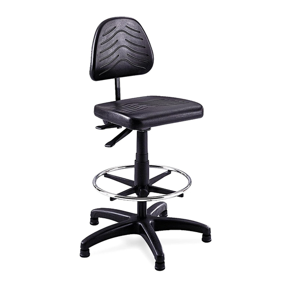
DESCRIPTION
CODE
A
Glide
B
Base
C
Cylinder
D
Foot Ring
E
Dust Cover (3 pc set)
Seat Assembly
F
G
Back Assembly
TOOLS REQUIRED: SCREWDRIVER
PRODUCT WARRANTY REGISTRATION
is available online at: www.safcoproducts.com
Check all parts against Parts List before
beginning assembly. Allow all parts to warm to
room temperature prior to assembly.
1
Install a A Glide into each of the legs of the B
Base. Press firmly into place. Be sure the glide is
inserted completely into leg for proper stability.
2
Insert the C Cylinder into the base, tapered end
down. Secure the cylinder by applying a little down-
ward pressure (CAUTION: When applying downward
pressure, avoid plastic button at top of cylinder, as
pressure will release pneumatic lift)
3
Slide D Foot Ring on to cylinder (ring side up),
position at desired height. Turn knob to secure.
Place E Dust Cover over exposed cylinder.
4
Install the F Seat Assembly by aligning the hole on
the underside with the shaft of the cylinder; push down
firmly on seat.
5
Insert the stem of the G Back Assembly into the slot
at the back of the seat. Use a screwdriver to depress
the push button at the bottom of the stem and slide
until the stem goes all the way through the slot and
sticks out the other side about 2". It may be necessary
to rotate the knob at the back of seat assembly
counterclockwise so stem will slide all the way through
the slot. Rotate the knob clockwise to lock the stem.
6
Make the final chair adjustments following the
instructions on the reverse side.
5113-37MP: 1 of 6; Rev. 3; 9/06
INDUSTRIAL CHAIR (19"-27" Range)
PARTS LIST
QTY.
PART NO.
5
5110-25
1
5100-04
1
5110-11
1
5110-06
1
5110-14
1
5113-51
1
5113-52
G
E
D
Registered U.S. Patent D381,823
MODEL
5113
NUMBER
F
C
B
A
8000.02
Publicidad

Resumen de contenidos para Safco TASK MASTER 5113
- Página 1 MODEL 5113 INDUSTRIAL CHAIR (19"-27" Range) NUMBER ASSEMBLY INSTRUCTIONS READ THESE INSTRUCTIONS BEFORE STARTING; FOLLOW THE ASSEMBLY PROCEDURES CAREFULLY. PARTS LIST LETTER DESCRIPTION QTY. PART NO. CODE Glide 5110-25 Base 5100-04 Cylinder 5110-11 Foot Ring 5110-06 Dust Cover (3 pc set) 5110-14 Seat Assembly 5113-51...
-
Página 2: General Safety Instructions
The pneumatic lift in the Cylinder is permanently lubricated at the factory and needs no further lubrication. NEVER LUBRICATE THE PNEUMATIC LIFT. Do not remove clip from bottom of Cylinder. Contact Safco immediately if clip Thank you for purchasing this Safco product. In order to make any warranty is missing or damaged. -
Página 3: Liste Des Pièces
CHAISE INDUSTRIELLE (GAMME DE NUMÉRO 5113 DE MODÈLE HAUTEURS DE 48 À 68 CM [19 À 27 PO]) INSTRUCTIONS DE MONTAGE LIRE CES INSTRUCTIONS AVANT DE COMMENCER. SUIVRE LES ÉTAPES DE MONTAGE AVEC SOIN. LISTE DES PIÈCES CODE DESCRIPTION QTÉ. DE PIÈCE ALPHABÉTIQUE Glissière... -
Página 4: Instructions De Réglage De La Chaise
à l’usine, et n’a pas besoin d’être graissé. NE JAMAIS GRAISSER L’ÉLÉVATEUR PNEUMATIQUE. Ne pas enlever la bague sur le dessous du cylindre, et communiquer avec Safco immédiatement si la bague Merci d’avoir acheté ce produit Safco. manque ou est endommagée. Nettoyer le siège et le Pour être en mesure de faire une... -
Página 5: Instrucciones De Ensamblaje
SILLA INDUSTRIAL MODELO 5113 NÚMERO (RANGO DE ALTURA DE 48 A 68 CM [19-27"]) INSTRUCCIONES DE ENSAMBLAJE POR FAVOR LEA ESTAS INSTRUCCIONES ANTES DE EMPEZAR Y SIGA CUIDADOSAMENTE EL PROCEDIMIENTO DE ENSAMBLAJE LISTA DE PIEZAS CLAVE DESCRIPCIÓN CANT. NO. DE PIEZA ALFABÉTICA Deslizador 5110-25... -
Página 6: Instrucciones Para Ajustar La Silla
NUNCA LUBRIQUE EL ELEVADOR NEUMÁTICO. No retire la pinza del extremo inferior del cilindro. Si falta o se daña esta pinza, comuníquese con Safco inmediatamente. Limpie el asiento de poliuretano con agua y jabón. Para reparar pequeñas rasgaduras Muchas gracias por comprar este en el poliuretano, aplique unas cuantas gotas de producto Safco.


