Tabla de contenido
Publicidad
Idiomas disponibles
Idiomas disponibles
Enlaces rápidos
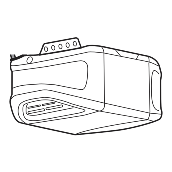
Installation
1
Before you begin
Your garage door opener has an internal gateway located on the receiver logic board. After installing the new receiver logic board, use the myQ
garage door opener to your myQ account. The products illustrated in the instructions are for reference. Your product may look different.
To prevent possible SERIOUS INJURY or
DEATH:
• Disconnect ALL electric and battery
power BEFORE performing ANY service
or maintenance.
To prevent damage to the receiver/logic
board, DO NOT touch printed circuit board
of replacement receiver/logic board during
installation.
ALWAYS wear protective gloves and eye
protection when changing the battery or
working around the battery compartment.
2
Remove the receiver logic board
2.1 Disconnect the wires from the quick-connect terminals (A).
Remove the receiver logic board end panel from the garage
door opener.
A
To insert or remove
the wires from the
terminal, push in the
tab with a
screwdriver tip.
1.1 Remove the light lens by pulling the
top sides of the light lens and rotate the
light lens down. Squeeze the light lens
clips to remove lens from end panel.
AVERTISSEMENT : Ce produit peut vous exposer à des produits chimiques, dont le plomb, qui sont reconnus par l'État de Californie
comme provoquant le cancer, des malformations congénitales ou d'autres problèmes de reproduction. Pour en savoir plus, visitez
www.P65Warnings.ca.gov.
2.2 Unplug the wire harnesses from the receiver logic
board. You may need needle-nosed pliers to remove
the harnesses.
RECEIVER LOGIC BOARD REPLACEMENT
1.2 To maintain your warranty, place the
provided label over the existing label
on the end panel of the garage door
opener.
TO ERASE ALL
RECEIVER CODES
1. Press and HOLD
receiver orange
ERASE button
6 seconds. Indicator
light will turn ON.
2. Release button
when light turns OFF.
PART NO.:
NO. DE PIEZA:
CANADA:
DATE:
THE CHAMBERLAIN
GROUP, INC., USA
Ensamblado en México
TO ERASE ALL
RECEIVER CODES
TODOS LOS CÓDIGOS DEL
ELIMINACIÓN DE
1. Press and HOLD
RECEPTOR
Assembled in Mexico
ERASE button
receiver orange
1. MANTENGA PRESIONADO
el botón naranja "ERASE"
6 seconds. Indicator
del receptor durante 6
light will turn ON.
segundos. La luz del
indicador se encenderá.
2. Release button
when light turns OFF.
2. Suelte el botón cuando la
132C2280-3D
PART NO.:
NO. DE PIEZA:
luz se apague.
CANADA:
DATE:
DANGER • PELIGRO
THE CHAMBERLAIN
GROUP, INC., USA
Ensamblado en México
Assembled in Mexico
132C2280-3D
2.3 Remove the receiver
logic board from the
end panel by removing
the 2 screws and
releasing the 2 clips.
1
Model 050ACTWFMC
serial number found on the provided label to add your
®
1.3 Disconnect power to the garage door
opener.
ELIMINACIÓN DE
TODOS LOS CÓDIGOS DEL
RECEPTOR
1. MANTENGA PRESIONADO
el botón naranja "ERASE"
del receptor durante 6
segundos. La luz del
indicador se encenderá.
2. Suelte el botón cuando la
luz se apague.
DANGER • PELIGRO
Wire clip
Clips
Screws
Publicidad
Tabla de contenido

Manuales relacionados para Chamberlain 050ACTWFMC


Resumen de contenidos para Chamberlain 050ACTWFMC
- Página 1 RECEIVER LOGIC BOARD REPLACEMENT Model 050ACTWFMC Installation Before you begin Your garage door opener has an internal gateway located on the receiver logic board. After installing the new receiver logic board, use the myQ serial number found on the provided label to add your ®...
- Página 2 Install new receiver logic board 3.2 Insert the antenna wires through 3.1 Connect the wire harnesses to the 3.3 Reinsert the wires. 3.4 Install the light lens by aligning with the holes in the end panel. Snap the new receiver logic board. When Door control wires: the hinges and snapping into place.
-
Página 3: Program The Travel
Adjustment Program the travel 1.1 Press and hold the Adjustment Button 1.2 Press and hold the UP Button until the 1.3 Once the door is in the desired until the UP Button begins to flash and/ door is in the desired UP position. UP position press and release the or a beep is heard. -
Página 4: Test The Safety Reversal System
Test the Safety Reversal System 3.1 With the door fully open, place a 1-1/2 3.2 Press the remote control push button If the door stops but does not reverse: inch (3.8 cm) board (or a 2x4 laid flat) to close the door. The door MUST 1. - Página 5 REMPLACEMENT DU RÉCEPTEUR DE LA CARTE MÈRE Modèle 050ACTWFMC Montage Avant de commencer Votre ouvre-porte de garage est muni d’une passerelle située sur la carte mère du récepteur. Après avoir installé la nouvelle carte mère du récepteur, pour ajouter votre ouvre-porte de garage à votre compte myQ utilisez le numéro de série de myQ situé...
- Página 6 Installez la nouvelle carte mère du récepteur 3.2 Enfilez les fils de l’antenne dans le 3.1 Connectez les fils du harnais à la 3.3 Insérez le fils à nouveau. 3.4 Installez la lentille de la lampe en panneau d’extrémité, par les trous. nouvelle carte mère du récepteur.
-
Página 7: Configuration De La Force Automatique
Réglage Programmez le déplacement 1.1 Appuyez sur le bouton de réglage et 1.2 Appuyez et maintenez le bouton UP 1.3 Lorsque la porte est dans la position maintenez bouton enfoncé jusqu’à (haut) jusqu’à ce que la porte soit dans HAUTE souhaitée, appuyez et relâchez ce que le bouton fléché... - Página 8 Faites un test pour vérifier le système d’inversion de sécurité 3.1 La porte étant complètement ouverte, 3.2 Appuyez sur le bouton poussoir de la Si la porte s’arrête mais ne se réouvre pas : placez une planche de 3,8 cm télécommande pour fermer la porte. La 1.
-
Página 9: Instalación
REEMPLAZO DE LA TARJETA LÓGICA DEL RECEPTOR Modelo 050ACTWFMC Instalación Antes de empezar Su abrepuertas de garaje tiene una pasarela interna en la tarjeta lógica del receptor. Después de instalar la nueva tarjeta lógica del receptor, utilice el número de serie de myQ que se encuentra en la ®... -
Página 10: Instalar La Tarjeta Lógica Del Receptor
Instalar la tarjeta lógica del receptor 3.2 Introduzca los cables de la antena a 3.1 Conecte los arneses del cable a la nueva 3.3 Vuelva a insertar los cables. 3.4 Instale la lente de luz alineándola con través de los orificios del panel del tarjeta lógica del receptor. -
Página 11: Programar El Recorrido
Ajuste Programar el recorrido 1.1 Mantenga presionado el botón de 1.2 Mantenga presionado el botón UP 1.3 Una vez que la puerta esté en la posición ajuste hasta que el botón UP (SUBIR) (SUBIR) hasta que la puerta alcance la UP (de SUBIDA) deseada, presione y comience a parpadear o se escuche un posición de SUBIDA deseada. -
Página 12: Probar El Sistema De Inversión De Seguridad
(y los sensores no están a más de 6” [15 cm] sobre el piso), llame a un técnico capacitado en sistemas de puertas. © 2022, The Chamberlain Group LLC. All Rights Reserved Tous droits réservés 114-5798-000 Todos los derechos reservados...