
Manuales relacionados para Zanussi ZHC590


Resumen de contenidos para Zanussi ZHC590
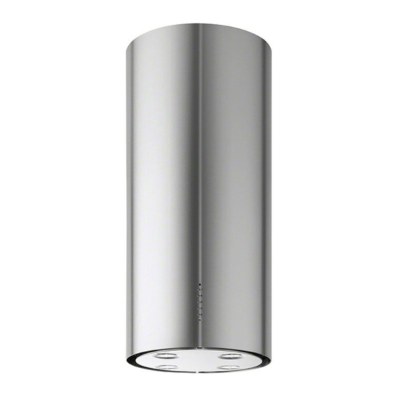
- Página 1 User Gebruiksaanwi- Manual de Manual de Manual jzing instrucciones Instruções Bedienungsanlei- tung Model ZHC590...
- Página 2 For the User For the Installer Technical Information Important Safety Information Electrical Connections Electrical Requirements Your Appliance Electrical Connection Operating Instructions Installing the Cooker Hood Cooker Hood Controls Installation Requirements To Operate Unpacking Recirculation Fitting the Wall Brackets Extraction Fitting the Canopy Hood Venting Maintenance and Cleaning Recirculation...
-
Página 3: Important Safety Information
Refer to your local Zanussi Ser- vice Force Centre. Always insist on genuine spare • If the room where the hood is to be used contains parts. -
Página 4: Your Appliance
YOUR APPLIANCE * Dimensions of the hood in ducting version. ** Dimensions of the hood in recycling version. -
Página 5: Control Panel
OPERATING INSTRUCTIONS The cooker hood is designed to extract unpleasant odours from the kitchen, it will not extract steam. The appliance can be installed to recirculate or extract contaminated air. Control Panel The hood can be switched on pushing directly onto the requested speed without fi rstly having to select 0/1 but- ton. - Página 6 OPERATING INSTRUCTIONS To Operate Select the required fan speed and light if required. Recirculation In the recirculation mode the contaminated air enters the cooker hood through the grease fi lters. The air is cleaned by passing through the charcoal fi lters before being passed back into the kitchen through the grilles in either side of the chimney stack.
-
Página 7: Maintenance And Cleaning
MAINTENANCE AND CLEANING Before carrying out any maintenance or clean- ing isolate the cooker hood from the mains supply. The cooker hood must be kept clean, as a build up of grease or fat can be a fi re hazard. External Cleaning Wipe the cooker hood frequently with warm soapy water using a mild detergent. - Página 8 MAINTENANCE AND CLEANING Before carrying out any maintenance or cleaning isolate the cooker hood from the mains supply. Charcoal Filters In the recirculation mode the charcoal fi lters absorb smells and unwanted odours. Enabling the alarm signal • In Recirculation version Hoods, the Filter saturation alarm can be enabled on installation or at a later date. •...
-
Página 9: Something Not Working
SOMETHING NOT WORKING If, having followed these instructions carefully, your cooker hood fails to work properly please carry out the following checks. Symptom Solution • Check the hood is connected to the electricity The cooker hood will not start supply. •... -
Página 10: Guarantee / Customer Service
GUARANTEE / CUSTOMER SERVICE Standard guarantee conditions We, Electrolux, undertake that if within 0870 5 929 929 12 months of the date of the purchase Your telephone call will be automatically routed to the this Electrolux appliance or any part thereof is proved Service Force Centre covering your postcode area. -
Página 11: Guarantee Conditions
GUARANTEE CONDITIONS Customer Care European Guarantee For general enquiries concerning your This appliance is guaranteed by Electrolux in each of Electrolux appliance, or for further information on the countries listed at the back of this user manual, Electrolux products please contact our Customer Care for the period specifi... - Página 12 Ireland +353 1 40 90 753 Long Mile Road Dublin 12 Italia +39 (0) 434 558500 C.so Lino Zanussi, 26 - 33080 Porcia (PN) Latvija +37 17 84 59 34 Kr. Barona iela 130/2, LV-1012, Riga Lietuva +370 5 2780609 Verkių...
-
Página 13: Installation Instructions
INSTALLATION INSTRUCTIONS It is dangerous to alter the specifi cations or attempt to modify this product in any way. Technical Information DIMENSIONS HEIGHT OF CANOPY: 935 mm HEIGHT OF CHIMNEY: (UPPER SECTION) 290 mm (LOWER SECTION) 935 mm WIDTH OF CANOPY : 370 mm DEPTH OF CANOPY: 370 mm... -
Página 14: Installation Requirements
INSTALLING THE COOKER HOOD Please ensure that when the appliance is installed it is easily accessible to an engineer in the event of a breakdown. All installations must comply with the local authorities requirements for the discharge of exhaust air. Incorrect installation may affect the safety of this cooker hood. - Página 15 INSTALLING THE COOKER HOOD Clearance Height The cooker hood is designed to be fi tted over a cook- ing appliance at the clearance heights stated, providing the maximum output of the appliance beneath does not exceed the maximums quoted in the Technical Speci- fi...
- Página 16 INSTALLING THE COOKER HOOD Drilling the Ceiling/Support Shelf • Use a plumb line to mark the centre of the hob on the ceiling/support shelf. • Place the drilling template 21 provided on the ceiling/ support shelf, making sure that the template is in the correct position by lining up the axes of the template with those of the hob.
- Página 17 INSTALLING THE COOKER HOOD Installation of components in recycling version: • Fix the recycling air outlet piece 15 to the upper part of the frame using four 12c screws supplied with the hood. • Fix the fl ange (ø120) 10 to the lower part of the recycling air outlet 15.
- Página 18 INSTALLING THE COOKER HOOD Ducting Connection Connect the ducting chosen to: • the Ø150mm ducting spigot on top of the motor housing, or the Ø150-120mm ducting spigot item 9 and secure using the jubilee clips item 25. 9 + 9a •...
-
Página 19: Electrical Connection
INSTALLING THE COOKER HOOD Chimney Stack The chimney consists of two sections. The lower chimney measures (with the Hood body and recirculation grilles) 935 mm and the upper chimney measures 290 mm. The overall installed measurement is min. 935 - max 1215 mm. Fitting the Upper Chimney and the Hood Body When the hood is installed in recycling version the... -
Página 20: Tabla De Contenido
Gebruiksaanwijzing INHOUDSOPGAVE ADVIEZEN EN SUGGESTIES ..............................21 EIGENSCHAPPEN ..................................22 INSTALLATIE ...................................24 GEBRUIK ....................................28 ONDERHOUD ..................................29... -
Página 21: Adviezen En Suggesties
ADVIEZEN EN SUGGESTIES Deze gebruiksaanwijzing geldt voor verschillende uitvoeringen van het apparaat. Het is mogelijk dat er een aantal kenmerken wor- den beschreven die niet van toepassing zijn op uw apparaat. INSTALLATIE • De fabrikant aanvaardt geen enkele aansprakelijkheid voor schade die voortkomt uit onjuiste of niet overeenkomstig de regels der kunst uitgevoerde installaties. -
Página 22: Eigenschappen
EIGENSCHAPPEN Buitenafmetingen * Afmetingen voor afzuigkap in afzuigversie. ** Afmetingen voor afzuigkap in fi lterversie. - Página 23 Onderdelen Ref. Aantal Productonderdelen Afzuigkap compleet met: Bedieningen, Li- chtgroep, Filters, Onderstuk Schouw Bovenstuk Schouw Telescopisch Frame compleet met Afzuig- groep bestaande uit: 7.1a Bovenstuk Frame 7.1b Onderstuk Frame Reductiefl ens ø 150-120 mm 7.1a Flens ø 125 mm Flens ø 120 mm Verbindingsstuk Luchtuitlaat Filterversie Leidingklemmen Ref.
-
Página 24: Installatie
INSTALLATIE Gaten boren in plafond/plank en bevestiging frame GATEN BOREN IN PLAFOND/PLANK • Teken met behulp van een looddraad op het plafond/de draagplank het midden van de kookplaat af. • Houd de bijgeleverde boormal 21 tegen het plafond/de plank, en laat het midden hiervan samenvallen met het afgetekende punt en lijn de assen van de boormal uit met de assen van de kookplaat. - Página 25 BEVESTIGING VAN HET FRAME Indien U de afzuigkap in fi lterversie wenst te installeren, dient U het frame te voorzien van alle nodige verbindingsstukken. Om de onderdelen voor de fi lterversie op een eenvoudige manier te kunnen monteren, dient U het frame te verlengen. U gaat hiervoor als volgt te werk: •...
- Página 26 BEVESTIGING FRAME • Til het frame op maar zorg ervoor dat de inkerving in de plaat van het frame naar voren is gericht. • Zet de haken van het frame over de twee schroeven die U eerder in het plafond plaatste en schuif tot in het midden van de haak.
-
Página 27: Elektrische Aansluiting
MONTAGE VAN DE SCHOUW EN BEVESTIGING VAN DE AFZUIGKAP De schouw dient gedraaid te worden met de haken naar boven gericht als U de afzuigkap in fi lterversie wenst te installeren, en met de haken naar beneden gericht als U de kap in afzuigversie wenst te installeren. -
Página 28: Gebruik
GEBRUIK Bedieningspaneel De wasemkap kan rechtstreeks ingeschakeld worden op de gewenste snelheid, door de desbetreffende toets in te drukken zonder eerst de toets 0/1 motor te bedienen. TOETS FUNCTIES 0/1 Licht Schakelt de verlichting aan en uit. T1 0/1 Motor brandt Eerste snelheid. -
Página 29: Onderhoud
ONDERHOUD Metalen Vetfi lters SCHOONMAAK VAN DE METALEN VETFILTERS Reset van het alarmsignaal • Schakel de lichten en de afzuigmotor uit. • Druk gedurende minstens 3 seconden op de toets T3, tot de led’s knipperen ter bevestiging. Schoonmaak van de Filters •... - Página 30 Geurfi lter (fi lterversie) Het fi lter kan niet gewassen en niet geregenereerd worden en moet worden vervangen wanneer de led S1 knippert o f minstens eenmaal in de 4 maanden. De alarmsignalering is alleen actief wanneer de afzuig- motor wordt gebruikt. Activering van het alarmsignaal •...
- Página 31 Manual de instrucciones ÍNDICE CONSEJOS Y SUGERENCIAS ............................32 CARACTERÍSTICAS ................................33 INSTALACIÓN ..................................35 USO ....................................39 MANTENIMIENTO ................................40...
-
Página 32: Consejos Y Sugerencias
CONSEJOS Y SUGERENCIAS Las presentes instrucciones de servicio son válidas para diferentes mo- delos de aparato; por ello puede ser posible que se describan detalles y características de equipamiento que no concuerden íntegramente con las de su aparato concreto. INSTALACIÓN •... -
Página 33: Características
CARACTERÍSTICAS Dimensiones * Dimensiones de la campana en versión aspirante. * * Dimensiones de la campana en versión fi ltrante. -
Página 34: Componentes
Componentes Ref. Cant. Componentes del Producto Cuerpo Campana completo de: Mandos, Iluminación, Filtros, Chimenea Inferior Chimenea superior Armazón telescópico completo de Aspira- dor, formado por: 7.1a Armazón superior 7.1b Armazón inferior Arandela de reducción ø 150-120 mm 7.1a Anillo adaptador ø120-125 mm Arandela ø... -
Página 35: Instalación
INSTALACIÓN Taladrado del cielorraso/repisa y fi jación del armazón metálico TALADRADO CIELORRASO/REPISA • Con la ayuda de un hilo de plomo marcar en el cielorraso/repisa de soporte el centro del plano de cocción. • Apoyar en el cielorraso/repisa la plantilla de taladrado 21 en dotación, haciendo coincidir su centro con el centro proyectado y alineando los ejes de la plantilla con los ejes del plano de cocción . - Página 36 PREPARACIÓN DEL ARMAZON PARA LA CON- EXION FILTRANTE En el caso de que se instale la campana en ver- sión fi ltrante hace falta predisponer en el armazón todos los empalmes necesarios para tal versión. Para facilitar la instalación de los particulares para la versión fi...
-
Página 37: Fijacion Armazon
FIJACION ARMAZON • Levantar el armazón teniendo cuidado de que el índice puesto sobre la lámina de éste se en- cuentre en la parte anterior. • Encajar los ojales del armazón en los dos torni- llos colocados anteriormente en el techo y girar hasta el centro del ojal de regulación. -
Página 38: Conexión Eléctrica
Montaje Chimenea y Sujeción Cuerpo Campana Es necesario girar la chimenea hacia arriba con los ojales hacia arriba en caso de instalación de la campana en versión fi ltrante, viceversa, con los ojales hacia abajo en caso de instalación en ver- sión aspirante. -
Página 39: Uso
Tablero de mandos La camapana puede encenderse directamente a la velocidad deseada, apretando el correspondiente pulsador sin pasar por el pulsador 0/1 motor. TASTO FUNCIONES 0/1 Luz Enciende y apaga la iluminación. T1 0/1 Motor encendido Primera velocidad. Apretándolo durante 1” apaga la campana. T2 Velocidad encendido Segunda velocidad. -
Página 40: Mantenimiento
MANTENIMIENTO Filtros antigrasa LIMPIEZA DE LOS FILTROS ANTIGRASA METALICOS Reset de la señal de alarma • Apagar las Luces y el Motor de aspiración. • Apretar el pulsante T3 durante 3 segundos, hasta el re- lampagueo de confi rmación de los leds. Limpieza de los fi... -
Página 41: Substitucion
Filtro antiolor (Versión Filtrante) No se puede lavar y no se regenera, se substituye cuando el led S1 relampaguea o cada 4 meses. La señal de Alarma se produce solo cuando se acciona el Motor de aspiración. Activación de la señal de alarma •... - Página 42 Manual de Instruções ÍNDICE CONSELHOS E SUGESTÕES ............................43 CARACTERÍSTICAS ................................44 INSTALAÇÃO ..................................46 UTILIZAÇÃO ..................................50 MANUTENÇÃO .................................. 51...
-
Página 43: Conselhos E Sugestões
CONSELHOS E SUGESTÕES Estas instruções de serviço aplicam-se a vários modelos de aparelhos. É. por isso, possível que se encontrem descritas várias características de equipamento que não dizem respeito ao seu aparelho. INSTALAÇÃO • O fabricante declina toda e qualquer responsabilidade pelos danos decorrentes de uma instalação não correcta ou feita não em conformidade com as normas da boa técnica. -
Página 44: Características
CARACTERÍSTICAS Dimensões * Dimensões para exaustor na versão aspirante. ** Dimensões para exaustor na versão fi ltrante. - Página 45 Componentes Ref. Qtd. Componentes do produto Corpo do exaustor equipado com: Coman- dos, luz, fi ltros e chaminé inferior Chaminé superior Armação telescópica com aspirador, com- posta de: 7.1a Armação superior 7.1b Armação inferior Flange de redução ø 150-120 mm 7.1a Anel ø120-125 Flange de ø120 mm...
-
Página 46: Instalação
INSTALAÇÃO Perfuração do tecto/prateleira e fi xação da armação PERFURAÇÃO DO TECTO/PRATELEIRA • Com a ajuda de um fi o de prumo, marque noTecto/Prateleira de suporte o ponto de projecção do centro da placa do fogão. • Apoie o gabarito de perfuração 21, que acompanha o aparelho, no tecto/prateleira de modo a fazer com que o centro deste coincida com o centro projectado e alinhando os eixos do gabarito com os eixos da placa do fogão. - Página 47 PREPARAÇÃO DA ARMAÇÃO PARA A CONEXÃO FILTRANTE No caso de se instalar o exaustor na versão fi ltrante, é necessário preparar na armação todas as conexões necessárias para esta versão. Para facilitar a instalação dos componentes específi cos para a versão fi ltrante, é necessário alongar a armação.
- Página 48 FIXAÇÃO DA ARMAÇÃO • Levante a armação, prestando atenção ao indicador sobre a placa da armação, que tem de estar na parte anterior. • Enfi e os orifícios oblongos da armação nos dois parafusos aplicados anteriormente no tecto e rode até...
-
Página 49: Ligação Eléctrica
Montagem da chaminé e fi xação do corpo do exaustor Se o exaustor for instalado na versão fi ltrante, a chaminé deverá ser montada com os orifícios ovais para cima. Se a instalação for feita na versão aspirante, os orifícios ovais deverão fi car para baixo. -
Página 50: Utilização
UTILIZAÇÃO Quadro de comandos Pode ligar-se o exaustor directamente, na velocidade pretendida, carregando no botão corres-pondente, sem ter de se carregar no botão 0/1 motor. TECLA FUNÇÕES Liga e desliga a iluminação. T1 0/1 Motor Fixo Primeira velocidade. Desliga o exaustor se for mantida premida por cerca de 1”. -
Página 51: Manutenção
MANUTENÇÃO Filtros metálicos antigordura LIMPEZA DOS FILTROS METÁLICOS ANTIGORDURA Como apagar o sinal de alarme • Desligue as luzes e o motor de sucção. • Prima a tecla T3 durante, pelo menos, 3 segundos, até os leds piscarem a confi rmar. Limpeza dos fi... -
Página 52: Substituição Das Lâmpadas
Filtro anti-odor (Versão Filtrante) Não pode ser lavado e não é regenerável, devendo ser substituído quando o led S1 se liga ou de 4 em 4 meses de utilização; com maior frequência se o aparelho for utilizado com muita intensidade. Activação do sinal de alarme •... - Página 53 Bedienungsanleitung INHALTSVERZEICHNIS EMPFEHLUNGEN UND HINWEISE ..........................54 CHARAKTERISTIKEN ............................... 55 MONTAGE ..................................57 BEDIENUNG ..................................61 WARTUNG ..................................62...
-
Página 54: Empfehlungen Und Hinweise
EMPFEHLUNGEN UND HINWEISE Diese Gebrauchsanleitung gilt für mehrere Geräte-Ausführungen. Es ist möglich, dass einzelne Ausstattungsmerkmale beschrieben sind, die nicht auf Ihr Gerät zutreffen. MONTAGE • Der Hersteller haftet nicht für Schäden, die auf eine fehlerhafte und unsach- gemäße Montage zurückzuführen sind. •... -
Página 55: Charakteristiken
CHARAKTERISTIKEN Platzbedarf * Abmessungen der Haube in Abluftversion. ** Abmessungen der Haube in Umluftversion. - Página 56 Komponenten Bez. Menge Produktkomponenten Haubenkörper komplett mit: Steuerungen, Beleuchtung, Filter, unterem Kaminteil Oberes Kaminteil Teleskopgitter komplett mit Sauggerät, bestehend aus: 7.1a Oberem Gitterteil 7.1b Unterem Gitterteil Reduktionsfl ansch ø 150-120 mm 7.1a Anschlussfl ansch ø 125 mm Filteranschlussstück Luftaustritt Rohrschellen Bez.
-
Página 57: Montage
MONTAGE Bohren der Decke/Trägerplatte und Montage des Teleskopgerüsts BOHREN DER DECKE/TRAGERPLATTE • Mit Hilfe eines Lots den Kochmulden-Mittelpunkt an der Decke oder Trägerplatte ermitteln und kennzeichnen. • Die mitgelieferte Bohrschablone 21 so auf die Decke/Trägerplatte legen, dass die Schablonenmitte mit dem gekennzeichneten Mittelpunkt übereinstimmt und die Schablonenseiten auf die Seiten der Kochmulde ausrich- ten. - Página 58 VORBEREITUNG DES GITTERS FÜR DEN AN- SCHLUSS IN UMLUFTVERSION Bei Montage der Haube in Umluftversion sind im Git- ter alle dafür notwendigen Anschlüsse vorzusehen. Zur Vereinfachung der Installation der Teile für die Umluftversion ist das Gitter zu verlängern. Dazu wie folgt vorgehen: •...
- Página 59 FIXIERUNG DES GITTERS • Das Gitter anheben. Dabei darauf achten, dass sich die Anzeige auf der Gitterplatte vorn befi ndet. • Die Langlöcher des Gitters an den zwei zuvor an der Decke angebrachten Schrauben einhaken und bis zur Mitte des Langlochs zur Regulierung drehen. •...
- Página 60 Montage des Kamins und Befestigung des Haubenkörpers Wird die Haube in Umluftversion installiert, den Kamin mit den Langlöchern nach oben drehen. Umgekehrt die Langlöcher für den Fall der Installation in Abluftversion nach unten drehen. • Das obere Kaminteil von unten nach oben einfügen und mit den 2 zuvor entfernten Schrauben am Gitter am oberen Teil befestigen.
-
Página 61: Bedienung
BEDIENUNG Bedienfeld Die Haube kann direkt auf die gewünschte Stufe eingeschaltet werden ohne daß man vorher auf die Gebläsetaste 0/1 drückt. TASTE FUNKTION 0/1 Beleuchtung Ein- und Ausschalten der Beleuchtung. T1 0/1 Motor Eingeschaltet Erste Geschwindigkeitsstufe. Schaltet die Haube aus wenn die Taste für ungefähr 1’’... -
Página 62: Wartung
WARTUNG Fettfi lter SELBSTTRAGENDER METALLFETTFILTER REINIGUNG Rücksetzen der Sättigungsanzeige • Licht und Gebläsemotor abschalten. • Mindestens 3 Sekunden lang die Taste T3 drücken, bis die Leds zur Bestätigung zu blinken beginnen. Filterreinigung • Die Filter können im Geschirrspüler gewaschen werden und sind dann zu reinigen, wenn die Led S1 zu sich einschalten beginnt bzw. -
Página 63: Auswechseln Der Lampen
Geruchsfi lter (Umluftversion) Dieser Filter kann weder gewaschen noch wiederverwendet werden und ist bei Blinken der Led S1 oder zumindest alle 4 Monate auszutauschen. Die Sättigungsanzeige erfolgt nur bei laufendem Gebläsemotor. Aktivierung der Sättigungsanzeige • Bei Hauben mit Umluftbetrieb erfolgt die Aktivierung der Sättigungsanzeige bei der Installation oder später. •... - Página 64 www.electrolux.com 436003685_04 - 070913...