Tabla de contenido
Publicidad
Idiomas disponibles
Idiomas disponibles
Enlaces rápidos
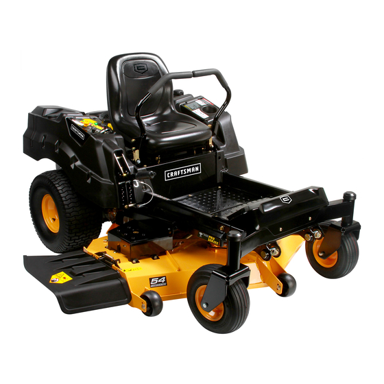
Operator's Manual
Zero-Turn Rider
24 HP, 48" MOWER DECK
Model No. 247.204201
• Espanol, P. 39
THIS product has a low emission engine which operates differently from
previously built engines. Before you start the engine, read and understand
this Operator's Manual.
CAUTION
Before using this equipment,
read this manual and follow
all safety rules and operating
instructions.
Sears Brands Management Corporation, Hoffman Estates, IL 60179 U.S.A.
Visit our website: www.craftsman.com
For answers to your questions about
this product, call:
1-888-331-4569
Customer Care Hot Line
Form No. 769-10440B
(March 25, 2015)
Publicidad
Tabla de contenido

Manuales relacionados para Sears Craftsman PRO Serie


Resumen de contenidos para Sears Craftsman PRO Serie
- Página 1 Before using this equipment, 1-888-331-4569 read this manual and follow all safety rules and operating Customer Care Hot Line instructions. Sears Brands Management Corporation, Hoffman Estates, IL 60179 U.S.A. Visit our website: www.craftsman.com Form No. 769-10440B (March 25, 2015)
-
Página 2: Warranty Statement
Normal deterioration and wear of the exterior finishes, or product label replacement. This warranty gives you specific legal rights, and you may also have other rights which vary from state to state. Sears Brands Management Corporation, Hoffman Estates, IL 60179 PRODUCT SPECIFICATIONS... -
Página 3: Safety Instructions
SAFETY INSTRUCTIONS WARNING DANGER This symbol points out important safety instructions which, if not This machine was built to be operated according to the safe operation followed, could endanger the personal safety and/or property of practices in this manual. As with any type of power equipment, yourself and others. -
Página 4: Slope Operation
SAFETY INSTRUCTIONS CHILDREN • Your machine is designed to cut normal residential grass of a height no more than 10”. Do not attempt to mow through unusually tall, dry grass (e.g., Tragic accidents can occur if the operator is not alert to the presence of children. pasture) or piles of dry leaves. -
Página 5: General Service
Federal laws apply on federal lands. • Keep all nuts, bolts, and screws tight to be sure the equipment is in safe A spark arrestor for the muffler is available through your nearest Sears Parts working condition. and Repair Service Center. -
Página 6: Safety Symbols
SAFETY INSTRUCTIONS SAFETY SYMBOLS This page depicts and describes safety symbols that may appear on this product. Read, understand, and follow all instructions on the machine before attempting to assemble and operate. Symbol Description READ THE OPERATOR’S MANUAL(S) Read, understand, and follow all instructions in the manual(s) before attempting to assemble and operate DANGER —... -
Página 7: Slope Gauge
SLOPE GAUGE... - Página 8 ASSEMBLY Set-Up Install Operator’s Seat To install the seat proceed as follows: NOTE: Remove the deck wash system nozzle adapter from the manual bag and store for future use. NOTE: The seat is shipped with the seat switch and seat pan attached. Moving The Riding Mower Manually Cut any straps securing the seat assembly and the drive control levers to the riding mower.
- Página 9 ASSEMBLY Position Drive Control levers Connecting the Battery Cables The drive control levers of the riding mower are lowered for shipping purposes. WARNING The flange lock nuts, hex screws, and flat washers that normally secure the control Battery posts, terminals, and related accessories contain lead and lead levers in their operating position are unfastened and installed in the slotted holes of compounds, chemicals known to the State of California to cause cancer and the control levers for shipment.
-
Página 10: Adjusting The Gauge Wheels
ASSEMBLY Lower Deck Discharge Chute Deflector Checking Tire Pressure WARNING WARNING Never operate the mower deck without the chute deflector installed and in Do not overinflate tires. Check sidewall of tires for maximum psi. Equal tire the down position. pressure should be maintained at all times. The discharge chute deflector must be installed before operating the mower. -
Página 11: Adjusting The Seat
ASSEMBLY Adjusting the Seat Adding Fuel To adjust the position of the seat, rotate the seat forward and locate the two WARNING adjustment knobs on the front of the seat pan. Refer to Figure 8. Use extreme care when handling gasoline. Gasoline is extremely flammable and the vapors are explosive. -
Página 12: Cup Holder
OPERATION LH Control Lever RH Control Lever Deck Lift Handle Deck Height Index Throttle Control Choke Control Cup Holder LCD Service Minder & Hour Meter PTO Knob Ignition Switch Module Fuel Tank Cap Fuel Level Window RH Transmission Bypass Rod LH Transmission Bypass Rod Figure 9 Cup Holder... -
Página 13: Ignition Switch Module
OPERATION Choke Control Power Take-Off (PTO) Knob The choke control is located on the RH console .The choke control The PTO knob is located on the RH console to the left of the determines the position of the engine choke. Pull the knob out to hour meter/indicator panel. -
Página 14: Low Battery
OPERATION LCD Service Minder & Hour Meter • Avoid slopes where possible. Never operate on slopes greater than 15°. Slopes with a greater incline present dangerous operating conditions. When the ignition key is rotated out of the STOP position but not into the START Tractors can be rolled over. -
Página 15: Starting The Engine
OPERATION • Start the tractor and move the control levers inward to the neutral operating • The safety interlock system will shut off the engine if the operator leaves position. Engage the PTO and move both control lever slowly into the slow the seat before the RH and LH drive control levers are fully outward in the neutral position engaging the parking brake. -
Página 16: Cold Weather Starting
OPERATION Cold Weather Starting Practice Operation (Initial Use) When starting the engine at temperatures near or below freezing, ensure the correct Operating a zero-turn tractor is not like operating a conventional type riding tractor. viscosity motor oil is used in the engine and the battery is fully charged. Start the Although and because a zero turn tractor is more maneuverable, getting used to engine as follows: operating the control levers takes some practice. - Página 17 OPERATION Turning the Tractor While Driving Forward Move the throttle control lever (if equipped) or throttle/choke control lever forward to the full throttle position. WARNING NOTE: Although the tractor’s engine is designed to run at full throttle, when performing a practice session the tractor must be operated at less than full When reversing the direction of travel, we recommend performing gradual throttle.
- Página 18 OPERATION Turning While Driving Rearward The greater the fore-to-aft distance between the two levers, the sharper the tractor will turn. To turn the tractor while driving rearward, move the control levers as necessary so To execute a “pivot turn,” move the turn side drive control lever to the that one lever is forward of the other.
- Página 19 OPERATION Reverse Caution Mode Executing a Zero Turn The REVERSE CAUTION MODE position of the key switch module allows the WARNING tractor to be operated in reverse with the blades (PTO) engaged. When executing a zero turn, the tractor MUST BE STOPPED. Executing a NOTE: Mowing in reverse is not recommended.
- Página 20 OPERATION Executing a “Y” Maneuver Driving On Slopes For low traction conditions, follow these procedures for zero turns (the Refer to the slope gauge in the Safe Operation Section to help determine slopes “Y-maneuver”): where you may not operate safely. To turn clockwise (front of machine moves toward RIGHT) when traveling WARNING FORWARD:...
-
Página 21: Deck Lift Lever
OPERATION When approaching the other end of the strip, slow down or stop before turning. A U-turn is recommended unless a pivot or zero turn is required. Align the mower with an edge of the mowed strip and overlap approximately 3”. Direct the tractor on each subsequent strip to align with a previously cut strip. -
Página 22: Service And Maintenance
Use the Service Log column to keep track of completed maintenance tasks. To Before performing any type of maintenance/service, disengage all controls schedule service from Sears Parts & Repair, call 1-888-331-4569. and stop the engine. Wait until all moving parts have come to a complete stop. -
Página 23: Engine Maintenance
SERVICE AND MAINTENANCE Tire Maintenance WARNING Check the tire air pressure after every 50 hours of operation or weekly. Keep the Before performing any maintenance or repairs, disengage the PTO, move tires inflated to the recommended pressures. Improper inflation will shorten the the drive control levers fully outward in the neutral position, engage the tire service life. - Página 24 SERVICE AND MAINTENANCE General Battery Information Remove the hex washer screw securing the battery hold-down bracket to the frame. Then flip the battery hold-down bracket up to free the battery. See Figure 24. WARNING Should battery acid accidentally splatter into the eyes or onto the skin, rinse the affected area immediately with clean cold water.
-
Página 25: Hydrostatic Transmission
1-888-331-4569 Pivot the operator’s seat forward and clean the reservoir cap and the area to have the electrical system checked by Sears Parts & Repair. around the cap to prevent debris from contaminating the transmission oil. - Página 26 SERVICE AND MAINTENANCE Adjustments Deck Leveling NOTE: Check the tractor’s tire pressure before performing any deck leveling CAUTION adjustments. Refer to Tires for information regarding tire pressure. Shut the engine off, remove the ignition key and engage the parking brake WARNING before making adjustments.
- Página 27 SERVICE AND MAINTENANCE Measure the distance from the front of the blade tip to the ground and the Remove the lock nut securing one of the front gauge wheel hex screws to the deck. Remove the gauge wheel, hex screw and spacer. See Figure 31. rear of the blade tip to the ground.
- Página 28 SERVICE AND MAINTENANCE Drive Control Lever Stop Adjustment Releasing Belt Tension with the Idler Pulley Using the deck lift handle, raise the deck to the position that provides When the drive control levers are both fully extended forward to the full-speed the most horizontal run of the belt between the deck idler pulleys and position and the tractor drifts left or right, the drive control lever stop adjustment the PTO pulley on the bottom of the engine.
-
Página 29: Deck Installation
SERVICE AND MAINTENANCE Rolling the Belt off the PTO Pulley Locate the LH and RH deck release pins on each side of the deck. Pull the release pins outward and release the deck from the LH and RH deck lift arms. Using the deck lift handle, raise the deck to the position that See Figure 36. -
Página 30: Replacing The Belt
SERVICE AND MAINTENANCE Make certain the belt is in the spindle pulleys of the deck, and that the Remove the two idler pulleys by removing the hex screws, washers and backside of the belt is against both the fixed and movable idler pulleys. flange lock nuts that secure them to the deck and the idler arm. -
Página 31: Transmission Drive Belt
Several components must be removed and special tools used in order to change the WARNING riding mower’s transmission drive belt. See your Sears Service Center or to schedule Before performing any maintenance, place the PTO switch in the “OFF” service, simply contact Sears at 1-888-331-4569. -
Página 32: Off-Season Storage
OFF-SEASON STORAGE WARNING Never store garden riding mower with fuel in tank indoors or in poorly ventilated areas where fuel fumes may reach an open flame, spark, or pilot light as on a furnace, water heater, clothes dryer, or gas appliance. Riding Mower Storage Sharpen the blades so that the mower will be ready to use when needed. - Página 33 Always wear safety glasses during operation or while performing any adjustments or repairs. This section addresses minor service issues. To locate the nearest Sears Service Center or to schedule service, simply contact Sears at 1-888-331-4569. Problem Cause...
- Página 34 TROUBLESHOOTING Problem Cause Remedy Engine overheats 1 . Engine oil level low 1 . Fill engine with proper amount and type of oil . 2 . Air flow restricted 2 . Clean grass clippings and debris from around the engine’s cooling fins and blower housing . Engine hesitates at high 1 .
-
Página 35: Ignition System
USED ELSEWHERE IN THE UNITED STATES (AND AFTER JANUARY 1, 2001 IN CANADA). California and United States Emission Control Defects Warranty Statement The California Air Resources Board (CARB), U.S. EPA and Sears are pleased to explain the control system on your engine for the periods of time listed below, provided there has Emission Control System Warranty on your model year 2000 and later small off-road been no abuse, neglect or improper maintenance of your small off-road engine. -
Página 36: Manufacturer'S Warranty Coverage
FEDERAL and/or CALIFORNIA EMISSION CONTROL WARRANTY STATEMENT YOUR WARRANTY RIGHTS AND OBLIGATIONS MTD Consumer Group Inc, the United States Environmental Protection Agency (EPA), and for those products certified for sale in the state of California, the California Air Resources Board (CARB) are pleased to explain the evaporative emission control system (ECS) warranty on your 2014-2015 small off-road equipment (outdoor equipment) . -
Página 37: Warranted Parts
WARRANTED PARTS: The repair or replacement of any warranted part otherwise eligible for warranty coverage may be excluded from such warranty coverage if MTD Consumer Group Inc demonstrates that the outdoor equipment has been abused, neglected, or improperly maintained, and that such abuse, neglect, or improper maintenance was the direct cause of the need for repair or replacement of the part . -
Página 38: Repair Protection Agreement
Discount of 25% from regular price of service and related installed parts not covered by the agreement; also, 25% off regular price of preventive maintenance check Fast help by phone – we call it Rapid Resolution – phone support from a Sears representative. Think of us as a “talking owner’s manual.”... -
Página 39: Tabla De Contenido
Deterioro y desgaste normal de los acabados exteriores, o el reemplazo etiqueta del producto. Esta garantía le otorga derechos legales específicos, y usted también puede tener otros derechos que varían de estado a estado. Sears Brands Management Corporation, Hoffman Estates, IL 60179 ESPECIFICACIONES DEL PRODUCTO N.º... -
Página 40: Proposición 65 De California
INSTRUCCIONES DE SEGURIDAD ADVERTENCIA PELIGRO La presencia de este símbolo indica que se trata de instrucciones de seguridad Esta máquina está diseñada para ser utilizada respetando las normas de importantes que debe respetar para evitar poner en riesgo su seguridad seguridad contenidas en este manual. -
Página 41: Funcionamiento En Pendiente
INSTRUCCIONES DE SEGURIDAD NIÑOS • Su máquina está diseñada para cortar césped residencial normal de una altura no mayor a 10 pulgadas. No intente cortar césped demasiado crecido, seco Pueden ocurrir accidentes trágicos si el operador no está atento a la presencia de niños. (por ejemplo, pastura) ni pilas de hojas secas. -
Página 42: Servicio General
Al finalizar la vida útil media haga inspeccionar anualmente esta todos los residuos embebidos en combustible. unidad por Sears u otro distribuidor calificado para cerciorarse de que todos los sistemas mecánicos y de seguridad funcionan correctamente y no tienen excesivo •... -
Página 43: Símbolos De Seguridad
INSTRUCCIONES DE SEGURIDAD SÍMBOLOS DE SEGURIDAD En esta página se presentan y describen los símbolos de seguridad que en este producto puede tener. Lea, entienda y siga todas las instrucciones incluidas en la máquina antes de intentar armarla y hacerla funcionar. Símbolo Descripción LEA LOS MANUALES DEL OPERADOR... -
Página 44: Guía Para La Operación En Pendientes
GUÍA PARA LA OPERACIÓN EN PENDIENTES... -
Página 45: Configuración
MONTAJE Configuración Instale el asiento del operador Para instalar el asiento proceda de la siguiente manera: NOTA: Retire el adaptador del pico del sistema de lavado de la plataforma y de la bolsa del manual, y guárdelos para uso futuro. NOTA: El asiento se envía con el interruptor de asiento y el contenedor del asiento acoplados. -
Página 46: Coloque Las Palancas De Control De La Transmisión En Posición
MONTAJE Coloque las palancas de control de la transmisión en posición Conexión de los cables de la batería Las palancas de control de la transmisión del tractor cortacésped se bajan para el envío. ADVERTENCIA Las tuercas de seguridad con brida, los tornillos hexagonales y las arandelas planas que normalmente fijan las palancas de control en su posición de funcionamiento se aflojan e Los bornes, los terminales y los accesorios relacionados de la batería contienen instalan en los orificios ranurados de las palancas de control para el envío. -
Página 47: Baje El Deflector Del Canal De Descarga De La Plataforma
MONTAJE Baje el deflector del canal de descarga de la plataforma Control de la presión de los neumáticos ADVERTENCIA ADVERTENCIA Nunca opere la plataforma de corte sin el deflector del canal de descarga No infle los neumáticos en exceso. Consulte en los laterales de los neumáticos la presión máxima en psi Se debe mantener una presión uniforme para todos instalado y en posición baja. -
Página 48: Gasolina Y Aceite
MONTAJE Ajuste del asiento Carga de combustible Para ajustar la posición del asiento, gírelo hacia adelante y ubique las dos perillas ADVERTENCIA de ajuste en el frente del contenedor del asiento. Consulte la Figura 8. Tenga mucho cuidado al trabajar con gasolina. La gasolina es sumamente inflamable y sus vapores pueden causar explosiones. -
Página 49: Funcionamiento
FUNCIONAMIENTO Palanca de control Palanca de control del lado derecho del lado izquierdo Manija de elevación de la plataforma Posicionamiento de la altura de la plataforma Control del acelerador Control del cebador Portacubeta LCD avisador de servicio y medidor horario Perilla de la toma de fuerza (PTO) Módulo de interruptor de encendido... -
Página 50: Módulo Del Interruptor De Encendido
FUNCIONAMIENTO Control del cebador Perilla de la toma de fuerza (PTO) TOMA DE FUERZA El control del cebador está ubicado en la consola del lado derecho. La perilla de la PTO está ubicada en la consola del lado derecho, Dicho control determina la posición del cebador del motor. Tire de la a la izquierda del medidor horario/panel indicador. -
Página 51: Lcd Avisador De Servicio Y Medidor Horario
FUNCIONAMIENTO LCD avisador de servicio y medidor horario • En lo posible evite las pendientes. Nunca opere en pendientes mayores de 15º. Las pendientes con mayor inclinación presentan condiciones de operación Cuando se gira la llave de encendido de la posición de parada, pero no a la posición de peligrosas. -
Página 52: Antes De Hacer Funcionar El Tractor
FUNCIONAMIENTO Con las dos palancas de control totalmente hacia afuera en la posición de punto • El sistema de bloqueo de seguridad evita que el motor intente arrancar o arranque muerto/con el freno de mano aplicado, active la toma de fuerza (PTO). Levántelas a menos que se muevan las palancas de control de transmisión del lado derecho desde el asiento del operador;... -
Página 53: Arranque Del Motor En Clima Frío
FUNCIONAMIENTO Arranque del motor en clima frío Practique el modo de operación con el tractor (uso inicial) Al arrancar el motor a temperaturas cercanas o inferiores al punto de congelamiento, Operar un tractor con radio de giro cero no es lo mismo que operar un tractor convencional. asegúrese de que se use aceite de motor de viscosidad correcta y que la batería tenga carga Si bien precisamente un tractor con radio de giro cero es más maniobrable, es necesario completa. -
Página 54: Giro Con El Tractor En Marcha Adelante
FUNCIONAMIENTO Giro con el tractor en marcha adelante Mueva la palanca de control del acelerador (si está equipada) o la palanca de control del acelerador/cebador hacia adelante hasta la posición de aceleración máxima. ADVERTENCIA NOTA: Si bien el motor del tractor se ha diseñado para funcionar a máxima Al invertir la dirección del desplazamiento, le recomendamos que en lo posible aceleración, cuando practica el tractor debe funcionar a menos del máximo. -
Página 55: Realizar Un Giro Mientras Se Conduce Marcha Atrás
FUNCIONAMIENTO Realizar un giro mientras se conduce marcha atrás Cuanto mayor sea la distancia de adelante hacia atrás entre las dos palancas, más cerrado será el giro que dará el tractor. Para que el tractor gire mientras se desplaza hacia atrás, mueva las palancas de control Para realizar un "giro de pivote", mueva la palanca de control del lado de giro según sea necesario para que una palanca quede más adelante que la otra. -
Página 56: Modo Marcha Atrás Con Precaución
FUNCIONAMIENTO Modo marcha atrás con precaución Giro de radio cero ADVERTENCIA La posición MODO DE PRECAUCIÓN EN MARCHA ATRÁS del módulo de la llave de contacto permite operar el tractor en marcha atrás con las cuchillas (PTO) enganchadas. Para realizar un giro de radio cero, el tractor SE DEBE DETENER. La realización de un giro de radio cero con el tractor en movimiento puede reducir NOTA: No se recomienda cortar el césped en marcha atrás. -
Página 57: Operación En Pendiente
FUNCIONAMIENTO Realización de una maniobra en “Y” Operación en pendiente Cuando existen condiciones de baja tracción, realice estos procedimientos para realizar Consulte indicador de pendiente en la Sección Funcionamiento Seguro para determinar giros de radio cero (la “maniobra en Y”): en qué... -
Página 58: Palanca De Elevación De La Plataforma
FUNCIONAMIENTO Cuando se acerque al otro extremo de la franja, reduzca la velocidad o deténgase antes de girar. Se recomienda realizar un giro en U a menos que sea necesario realizar un giro de radio cero. Alinee la cortadora de césped con un borde de la franja cortada y superponga la pasada aproximadamente 3 pulgadas. -
Página 59: Servicio Y Mantenimiento
Llame al 1-888-331-4569 para programar el servicio del servicio de las piezas móviles. Desconecte el cable de la bujía y póngalo haciendo masa piezas y reparaciones de Sears. contra el motor para evitar que se encienda accidentalmente. Utilice siempre anteojos de seguridad durante el funcionamiento o mientras ajusta o repara este equipo. -
Página 60: Mantenimiento Del Motor
SERVICIO Y MANTENIMIENTO Mantenimiento de los neumáticos ADVERTENCIA Controle la presión de aire de los neumáticos cada 50 horas de operación o una vez por Antes de realizar tareas de mantenimiento o reparaciones, desconecte la toma semana. Mantenga los neumáticos inflados a las presiones recomendadas. El inflado de fuerza (PTO), mueva las palancas de control totalmente hacia afuera hasta la inadecuado de un neumático reduce su vida útil. -
Página 61: Información General Sobre La Batería
SERVICIO Y MANTENIMIENTO Información general sobre la batería Extraiga el tornillo de la arandela hexagonal que sujeta el soporte de sujeción de la batería al marco. TLuego levante el soporte de sujeción de la batería para liberar la batería. Vea la Figura 24. ADVERTENCIA En caso de que se produzca una salpicadura accidental de ácido en los ojos o la piel, enjuague el área afectada inmediatamente con agua limpia fría. -
Página 62: Mantenimiento Del Sistema Eléctrico
En condiciones operativas normales, no es necesario controlar el nivel de aceite del 1-888-331-4569 para que el servicio de piezas y reparaciones de Sears controle el depósito de expansión y no hace falta aceite adicional. Si controla el nivel de aceite sistema eléctrico. -
Página 63: Nivelación De La Plataforma (De Lado A Lado)
SERVICIO Y MANTENIMIENTO Ajustes Nivelación de la plataforma NOTA: Controle la presión de neumáticos del tractor antes de realizar cualquier nivelación PRECAUCIÓN de la plataforma. Consulte la sección Neumáticos para obtener información sobre la presión de los neumáticos. Apague el motor, retire la llave de encendido y coloque el freno de mano antes de realizar ajustes. -
Página 64: Ajuste De Las Ruedas De Calibración Delanteras
SERVICIO Y MANTENIMIENTO Estacione el tractor en una superficie firme y plana y coloque la manija de Retire la tuerca de seguridad que fija uno de los tornillos hexagonales de las ruedas de calibración delanteras a la plataforma. Retire la rueda de calibración, elevación de la plataforma en una posición intermedia. -
Página 65: Retiro De La Plataforma
SERVICIO Y MANTENIMIENTO Ajuste de detención de las palancas de control de la transmisión Para aflojar la tensión de la correa con la polea loca. Usando la manija de elevación de la plataforma, levante la plataforma a Cuando ambas palancas de control de la transmisión están completamente extendidas la posición que le ofrece mayor recorrido horizontal de la correa entre las hacia adelante hasta la posición de velocidad máxima y el tractor se desplaza a la poleas locas de la plataforma y la polea de la PTO en la base del motor. -
Página 66: Instalación De La Plataforma
SERVICIO Y MANTENIMIENTO Haciendo rodar la correa para sacarla de la polea de la toma de fuerza Ubique los pasadores de liberación de la plataforma del lado izquierdo y del lado (PTO). derecho que se encuentran a cada lado de la plataforma. Tire de los pasadores de liberación hacia afuera y suelte la plataforma de los brazos de elevación del lado Usando la manija de elevación de la plataforma, levante la plataforma a derecho e izquierdo de la plataforma. -
Página 67: Cambio De La Correa
SERVICIO Y MANTENIMIENTO Asegúrese de que la correa en ‘V’ esté en las poleas del husillo de la plataforma, Extraiga las dos poleas locas, para lo cual debe retirar los tornillos de cabeza luego oriente la correa hacia atrás por debajo del bastidor del tractor , por hexagonal y las tuercas de seguridad con brida que las sujetan a la plataforma encima de los tubos de transmisión, hacia la polea de la PTO en la base del y el brazo de polea loca. -
Página 68: Correa De Transmisión
Si el borde de corte de una cuchilla ya se ha afilado muchas veces, o si hay alguna separación en el metal, se recomienda instalar cuchillas nuevas. Puede adquirir las nuevas cuchillas al servicio de piezas y reparaciones de Sears o llamando al 1-888-331- 4569. -
Página 69: Almacenamiento Fuera De Temporada
ALMACENAMIENTO FUERA DE TEMPORADA ADVERTENCIA Nunca almacene el tractor cortacésped con combustible en el tanque en un espacio cerrado o en áreas poco ventiladas donde los gases del combustible puedan llegar a una llama expuesta, una chispa o un piloto como el que tienen algunos hornos, calentadores de agua, secadores de ropa o algún artefacto a gas. -
Página 70: Solución De Problemas
En esta sección se analizan problemas menores de servicio. Para ubicar el Centro de Servicio Sears más cercano o para programar un servicio, simplemente comuníquese con Sears al teléfono 1-888-331-4569. - Página 71 SOLUCIÓN DE PROBLEMAS Problema Causa Solución El motor recalienta 1 . El nivel de aceite del motor está bajo . 1 . Llene el motor con cantidad y tipo de aceite adecuados . 2 . Flujo de aire restringido 2 . Elimine los recortes de césped y los desechos de alrededor de las aletas de enfriamiento del motor y de la carcasa del soplador .
-
Página 72: Declaración De Garantía Sobre Defectos En El Control De Emisiones Para California Y Los Estados Unidos
Las siguientes son disposiciones específicas relacionadas con la cobertura de la garantía para Sin cargo defectos en el control de emisiones. Es un añadido a la garantía de motor Sears para motores no La reparación o reemplazo de cualquier parte con garantía se realizará sin cargo alguno regulados que se encuentra en las instrucciones de funcionamiento y mantenimiento. -
Página 73: Cobertura De La Garantía Del Fabricante
DECLARACIÓN FEDERAL y/o DE CALIFORNIA SOBRE GARANTÍAS EN EL CONTROL DE EMISIONES SUS DERECHOS Y OBLIGACIONES EN CUANTO A LA GARANTÍA MTD Consumer Group Inc, la Agencia de Protección Medioambiental de los Estados Unidos (EPA), y para aquellos productos certificados para su venta en el estado de California, el Departamento de los Recursos del Aire de California (CARB) se complacen en explicar la garantía que evaporativo sistema de control de emisiones (ECS) de su equipo (equipos de exteriores) de encendido por chispa para todo terreno, pequeño, de exteriores del año 2014-2015 . -
Página 74: Piezas Garantizadas
Durante la totalidad del período de garantía del motor y equipo para todo terreno arriba mencionado, MTD Consumer Group Inc mantendrá un suministro de piezas bajo garantía suficiente para satisfacer la demanda esperada de tales piezas . Cualquier pieza de reemplazo se podrá usar para el cumplimiento del mantenimiento o las reparaciones bajo garantía y se suministrarán sin cargo para el propietario . - Página 75 El *Coverage en Canadá varía en algunos artículos. Para detalles llenos la llamada Chamusca Canadá en 1-800- 361-6665. Servicio de instalación de Sears Si desea solicitar la instalación profesional de Sears de aparatos domésticos, dispositivos para abrir portones, calentadores de agua y otros artículos domésticos importantes, en los Estados Unidos o Canadá llame al 1-800-4-MY-HOME®.
- Página 76 ® Registered Trademark / Trademark of KCD IP, LLC in the United States, or Sears Brands, LLC in other countries ® Marca Registrada / Marca de Fábrica de KCD IP, LLC en Estados Unidos, o Sears Brands, LLC in otros países...