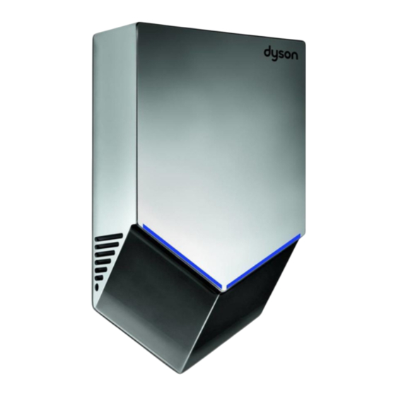
Dyson AB12 Guia De Instalacion
Ocultar thumbs
Ver también para AB12:
- Guia de instalacion (64 páginas) ,
- Manual de uso (97 páginas) ,
- Manual del propietário (61 páginas)
Resumen de contenidos para Dyson AB12
- Página 1 Installation Guide Guía de instalación Free 5 year warranty Register your warranty at www.dysonairblade.com...
-
Página 2: Important Safety Instructions
• The unit requires a 15 amp circuit breaker with a dedicated line and neutral. • Dyson will not be held liable for any damage to property or personal injury as a failure to comply with the instructions contained herein. -
Página 3: Instrucciones Importantes De Seguridad
• Dyson recomienda el uso de ropa, gafas y materiales de protección al instalar o reparar según sea necesario. El trabajo de instalación y conexión eléctrica debe realizarlo un electricista calificado conforme las leyes locales, estatales y federales y los estándares y códigos aplicables, incluso las... - Página 4 (A back panel for this product the unit and the floor. remove the rubber grommet from the rear is available from Dyson.) 3. Measure the location on the wall. If electrical electrical wiring entry hole. Store safely. wiring entry is to be from the rear, the electrical wiring from the wall must align with rear electrical wiring entry point in the backplate.
- Página 5 Rear electrical wiring entry. 0.25” ● Primary fixing locations (x4). Do not use countersunk screws. 4. Mark the location on the wall with a pencil. Fixing the backplate to the wall. 2. Pull the electrical wiring through the Use the backplate to mark the locations for the Fit the backplate securely to the wall using the grommet.
- Página 6 0.25” Side electrical wiring entry. Left right ● Primary fixing locations (x4). Do not use countersunk screws. 5th hole for side entry ● Important 1. Ensure you work only on the side of the guide when drilling. Ensure no pipe work 8.
- Página 7 Connecting to terminal block. Attaching main body. WArning: risk of electric shock! indicated on the terminal block holder. CAution: Do not overtighten screws. Do not use sealant when fixing the unit to the 4. Verify the connections are correct before wall.
- Página 8 8,7 pulgadas en los laterales. de goma del orificio de entrada posterior del (Se encuentra disponible un panel trasero de No debe haber obstrucciones entre la unidad cableado eléctrico. Guarde en un lugar seguro. Dyson para este producto). y el piso.
- Página 9 Entrada posterior del cableado eléctrico. 0,25 pulgadas ● Ubicaciones de los elementos de fijación primarios (x4). No utilice tornillos avellanados. 3. Mida la ubicación en la pared. Si la entrada Colocación de la placa posterior en la pared. 2. Coloque el cableado eléctrico a través de del cableado eléctrico se realiza desde la Fije la placa posterior firmemente a la pared la arandela.
- Página 10 0,25 pulgadas Entrada lateral del Izquierda Derecha cableado eléctrico. ● Ubicaciones de los elementos de fijación primarios (x4). No utilice tornillos avellanados. Quinto orificio para entrada lateral. ● IMPORTANTE La entrada del cableado eléctrico puede realizarse desde la derecha o la 1.
- Página 11 Conexión al bloque de terminales. Ajuste del cuerpo principal. ADVERTENCIA: Riesgo de choque eléctrico. eléctrico. 5. Pruebe la unidad para verificar si funciona PRECAUCIÓN: No ajuste los tornillos de más. Asegúrese de que la alimentación eléctrica 3. Abra la lengüeta del soporte del bloque de correctamente.
- Página 12 Dyson Customer Care Helpline If you have any questions on the installation please call us toll free at 1-888-DYSON-AB Línea directa de Asistencia al (1-888-397-6622). cliente de Dyson Si tiene alguna pregunta sobre la instalación, llámenos a este número de acceso gratuito: 1-888-DYSON-AB (1-888-397-6622).


