Tabla de contenido
Publicidad
Idiomas disponibles
Idiomas disponibles
Enlaces rápidos
Thank you for choosing Air Conditioners, please read this owner's manual carefully before
operation and retain it for future reference.
GREE reserves the right to interpret this manual which will be subject to any change due to
product improvement without further notice.
GREE Electric Appliances, Inc. of Zhuhai reserves the final right to interpret this manual. If
you have lost the Owner's Manual, please contact the local agent or visit www.gree.com or
sent email to global@gree.com.cn or electronic version.
Copyright 2018. This translation is property of GREE PRODUCTS SL. All rights reserved. Total or partial reproduction without its express authorization is prohibited.
INSTALLATION AND OPERATION MANUAL
FOR AHU-KIT UNIT
Owner's Manual
Air Conditioners
Models:
GMV-N140U/A-T
GMV-N280U/A-T
GMV-N560U/A-T
Gree Electric Appliances, Inc. of Zhuhai
Publicidad
Capítulos
Tabla de contenido

Manuales relacionados para Gree GMV-N140U/A-T


Resumen de contenidos para Gree GMV-N140U/A-T
- Página 1 Owner’s Manual, please contact the local agent or visit www.gree.com or sent email to global@gree.com.cn or electronic version. Copyright 2018. This translation is property of GREE PRODUCTS SL. All rights reserved. Total or partial reproduction without its express authorization is prohibited.
- Página 2 They can take this product for environmental safe recycling. Copyright 2018. This translation is property of GREE PRODUCTS SL. All rights reserved. Total or partial reproduction without its express authorization is prohibited.
-
Página 3: Tabla De Contenido
6.4 Disposal Requirements .................... 25 7 Table of Error Codes for Indoor Unit ..............25 8 Troubleshooting ....................26 Copyright 2018. This translation is property of GREE PRODUCTS SL. All rights reserved. Total or partial reproduction without its express authorization is prohibited. -
Página 4: Safety Precautions
Copyright 2018. This translation is property of GREE PRODUCTS SL. All rights reserved. Total or partial reproduction without its express authorization is prohibited. - Página 5 Gree Electric Appliances, Inc. of Zhuhai. Copyright 2018. This translation is property of GREE PRODUCTS SL. All rights reserved. Total or partial reproduction without its express authorization is prohibited.
-
Página 6: Product Introduction
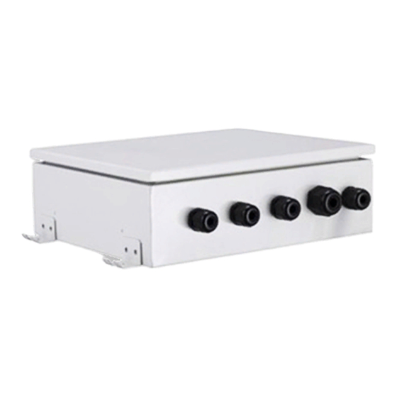
2.1 Names of Key Components Fig.2.1 ① ② Name Control Box Expansion valve kit Box 2.2 Overall System Connection Diagram Fig.2.2 Copyright 2018. This translation is property of GREE PRODUCTS SL. All rights reserved. Total or partial reproduction without its express authorization is prohibited. -
Página 7: Preparations For Installation
Please use the supplied standard fittings listed below as instructed. Name Appearance Quantity Magnetic ring Swell screw Copyright 2018. This translation is property of GREE PRODUCTS SL. All rights reserved. Total or partial reproduction without its express authorization is prohibited. -
Página 8: Selecting The Air Handling Unit
The corresponding AHU-KIT unit needs to be selected for your air handling unit. Select the AHU-KIT unit according to the above limitations. Copyright 2018. This translation is property of GREE PRODUCTS SL. All rights reserved. Total or partial reproduction without its express authorization is prohibited. -
Página 9: Location For Installation
(6) The installation site should be far away from heat source, inflammable gas and smoke. Copyright 2018. This translation is property of GREE PRODUCTS SL. All rights reserved. Total or partial reproduction without its express authorization is prohibited. -
Página 10: Requirements For Communication Wire
L ≤ 250 2×0.75 ~ 2×1.25 PVC Jacket Soft Wire the environment of strong magnetic or interference. Copyright 2018. This translation is property of GREE PRODUCTS SL. All rights reserved. Total or partial reproduction without its express authorization is prohibited. -
Página 11: Wiring Requirements
③ Install cut-off device near the unit. The minimum distance between each stage of cut-off device should be 3 mm (The same for both indoor unit and outdoor unit). Copyright 2018. This translation is property of GREE PRODUCTS SL. All rights reserved. Total or partial reproduction without its express authorization is prohibited. -
Página 12: Installation Instructions
(1) Size of control box for GMV-N140U/A-T、GMV-N280U/A-T and GMV-N560U/A-T (Unit: mm): Fig.4.1.1 Maintenance space of control space (Unit: mm): Fig.4.1.2 Copyright 2018. This translation is property of GREE PRODUCTS SL. All rights reserved. Total or partial reproduction without its express authorization is prohibited. - Página 13 Size of EXV box for GMV-N560U/A-T (Unit: mm): Fig.4.1.4 Maintenance space of EXV box (Unit: mm): Fig.4.1.5 Copyright 2018. This translation is property of GREE PRODUCTS SL. All rights reserved. Total or partial reproduction without its express authorization is prohibited.
-
Página 14: Piping Installation
Φ16.3mm. It needs engineering treatment on the scene if you want to connect liquid pipe of Φ12.7mm( expanding the copper tube of Φ12.7mm or using a connection copper tube) in order to Copyright 2018. This translation is property of GREE PRODUCTS SL. All rights reserved. Total or partial reproduction without its express authorization is prohibited. - Página 15 Part to be welded Taping Hands valve Pressure-reducing valve Nitrogen (3) For details, see manual of the outdoor unit. Notes: Copyright 2018. This translation is property of GREE PRODUCTS SL. All rights reserved. Total or partial reproduction without its express authorization is prohibited.
-
Página 16: Exv Installation
① Make sure to cool the filters and valve body with a wet cloth and make sure the body Copyright 2018. This translation is property of GREE PRODUCTS SL. All rights reserved. Total or partial reproduction without its express authorization is prohibited. -
Página 17: Installation Of The Control Box
② The cables require an additional pull relief. Fixing the cable with the wire clamp. Copyright 2018. This translation is property of GREE PRODUCTS SL. All rights reserved. Total or partial reproduction without its express authorization is prohibited. - Página 18 ① The H, M, L of fan gear lines and the 1, 2 of Lines of fault signal from external feedback Copyright 2018. This translation is property of GREE PRODUCTS SL. All rights reserved. Total or partial reproduction without its express authorization is prohibited.
-
Página 19: Installation Of The Thermistors
② Gas RT2 Installation of the thermistor cable (1) The length of thermistor wire is 10 m. Copyright 2018. This translation is property of GREE PRODUCTS SL. All rights reserved. Total or partial reproduction without its express authorization is prohibited. - Página 20 (2) Cover the thermistor with rubber belt to prevent looseness of temperature sensor. ’ Fig.4.5.1.5 (3) Use two wire ties to bind the thermistor securely. Copyright 2018. This translation is property of GREE PRODUCTS SL. All rights reserved. Total or partial reproduction without its express authorization is prohibited.
-
Página 21: Installation Of The Exv Cable
Be sure that the cable is fixed firmly in order to ensure a good pull relieve and water protection. Copyright 2018. This translation is property of GREE PRODUCTS SL. All rights reserved. Total or partial reproduction without its express authorization is prohibited. -
Página 22: Installation Of Wired Controller
⑨ Do not alter the inner wires of air conditioner. Manufacturer does not assume responsibility for damage or abnormal operation due to this reason. Copyright 2018. This translation is property of GREE PRODUCTS SL. All rights reserved. Total or partial reproduction without its express authorization is prohibited. -
Página 23: Connect Cables And Terminals Of Wiring Board
5.2 Power Cord Connection Notes! Power supply of each indoor unit must be from the same source. Copyright 2018. This translation is property of GREE PRODUCTS SL. All rights reserved. Total or partial reproduction without its express authorization is prohibited. -
Página 24: Connection Of Communication Wire Between Indoor Unit And Outdoor Unit (Or Indoor Unit)
ODU. Fig.5.3.1 Fig.5.3.2 5.4 Connect Communication Wire of Wired Controller Open electric box cover of indoor unit. Copyright 2018. This translation is property of GREE PRODUCTS SL. All rights reserved. Total or partial reproduction without its express authorization is prohibited. -
Página 25: Illuminate For Connection Of Wired Controller And Indoor Units (Ahu-Kit) Network
Address 2 is for slave controller. Detailed settings please refer to the instruction manual of wired controller. Copyright 2018. This translation is property of GREE PRODUCTS SL. All rights reserved. Total or partial reproduction without its express authorization is prohibited. - Página 26 OPERATING INSTALLATION MANUAL FOR AHU-KIT UNIT Fig.5.5 Copyright 2018. This translation is property of GREE PRODUCTS SL. All rights reserved. Total or partial reproduction without its express authorization is prohibited.
-
Página 27: Operation And Maintenance
(1) Check if the air inlet and air outlet of indoor and outdoor unit are blocked. (2) Check if securely grounded. Copyright 2018. This translation is property of GREE PRODUCTS SL. All rights reserved. Total or partial reproduction without its express authorization is prohibited. -
Página 28: Maintenance After The Seasonal Use
Unit Error Error Power Insufficiency Filter Cleaning Humidity Sensor Error Protection Reminder Special Code: Field Debugging Code Copyright 2018. This translation is property of GREE PRODUCTS SL. All rights reserved. Total or partial reproduction without its express authorization is prohibited. -
Página 29: Troubleshooting
If air conditioner still fails to work normally after checking and handling as described above, please stop using it immediately and contact local service center for assistance. Copyright 2018. This translation is property of GREE PRODUCTS SL. All rights reserved. Total or partial reproduction without its express authorization is prohibited. -
Página 30: Aires Acondicionados
Copyright 2018. This translation is property of GREE PRODUCTS SL. All rights reserved. Total or partial reproduction without its express authorization is prohibited. - Página 31 Éstos se encargarán de reci- clar su producto de modo seguro para el medio ambiente. Copyright 2018. This translation is property of GREE PRODUCTS SL. All rights reserved. Total or partial reproduction without its express authorization is prohibited.
- Página 32 7 Tabla de códigos de error para la unidad interior ..........25 8 Solución de problemas ..................26 Copyright 2018. This translation is property of GREE PRODUCTS SL. All rights reserved. Total or partial reproduction without its express authorization is prohibited.
-
Página 33: Indicaciones De Seguridad
Copyright 2018. This translation is property of GREE PRODUCTS SL. All rights reserved. Total or partial reproduction without its express authorization is prohibited. - Página 34 Copyright 2018. This translation is property of GREE PRODUCTS SL. All rights reserved. Total or partial reproduction without its express authorization is prohibited.
-
Página 35: Información Del Producto
Termistor (aire) Retorno de aire Suministro de aire Tubo de gas Termistor (salida) Controlador por cable Fig. 2.2 Copyright 2018. This translation is property of GREE PRODUCTS SL. All rights reserved. Total or partial reproduction without its express authorization is prohibited. -
Página 36: Manejo Y Mantenimiento
(1) Compruebe si la entrada y la salida de aire de las unidades interior y exterior están blo- queadas. (2) Compruebe si la unidad está bien conectada a tierra. Copyright 2018. This translation is property of GREE PRODUCTS SL. All rights reserved. Total or partial reproduction without its express authorization is prohibited. -
Página 37: Mantenimiento Después De La Temporada De Uso
Error de sensor Recordatorio de limpieza de suministro de humedad de filtro Código especial: Código de diagnóstico de campo Copyright 2018. This translation is property of GREE PRODUCTS SL. All rights reserved. Total or partial reproduction without its express authorization is prohibited. -
Página 38: Solución De Errores
Copyright 2018. This translation is property of GREE PRODUCTS SL. All rights reserved. Total or partial reproduction without its express authorization is prohibited. - Página 39 à global@gree.com.cn pour la version électronique. Copyright 2018. This translation is property of GREE PRODUCTS SL. All rights reserved. Total or partial reproduction without its express authorization is prohibited.
- Página 40 Ce dernier peut récupérer le produit en vue d'un recyclage respectueux de l'environnement. Copyright 2018. This translation is property of GREE PRODUCTS SL. All rights reserved. Total or partial reproduction without its express authorization is prohibited.
- Página 41 6.4 Exigences de mise au rebut ..................25 7 Tableau des codes d'erreur de l'unité intérieure ........... 25 8 Dépannage ......................26 Copyright 2018. This translation is property of GREE PRODUCTS SL. All rights reserved. Total or partial reproduction without its express authorization is prohibited.
-
Página 42: Précautions De Sécurité
être le boîtier extérieur du climatiseur). utilisée. Copyright 2018. This translation is property of GREE PRODUCTS SL. All rights reserved. Total or partial reproduction without its express authorization is prohibited. - Página 43 Copyright 2018. This translation is property of GREE PRODUCTS SL. All rights reserved. Total or partial reproduction without its express authorization is prohibited.
-
Página 44: Présentation Du Produit
Thermistance (Entrée) Thermistance (Air) Retour d'air Arrivée d’air Tuyau de gaz Thermistance (Sortie) Commande filaire Fig. 2.2 Copyright 2018. This translation is property of GREE PRODUCTS SL. All rights reserved. Total or partial reproduction without its express authorization is prohibited. -
Página 45: Préparatifs De L'iNstallation
Veuillez utiliser les pièces standard fournies listées ci-dessous comme indiqué : N° Apparence Quantité Anneau magnétique Boulon expansible Copyright 2018. This translation is property of GREE PRODUCTS SL. All rights reserved. Total or partial reproduction without its express authorization is prohibited. -
Página 46: Sélection De L'uNité De Traitement De L'aIr
L’unité AHU-KIT correspondante doit être sélectionnée pour votre unité de traitement de l’air. Sélectionner l’AHU-KIT en fonction des limitations ci-dessus. Copyright 2018. This translation is property of GREE PRODUCTS SL. All rights reserved. Total or partial reproduction without its express authorization is prohibited. -
Página 47: Emplacement De L'iNstallation
(6) L’emplacement de pose doit être éloigné de toute source de chaleur, gaz inflammable et fumée. Copyright 2018. This translation is property of GREE PRODUCTS SL. All rights reserved. Total or partial reproduction without its express authorization is prohibited. -
Página 48: Exigences Du Câble De Communication
L ≤ 250 2×0,75 ~ 2×1,25 dans un milieu présentant fin blindé/commun de fortes ondes magnétiques ou des interférences. Copyright 2018. This translation is property of GREE PRODUCTS SL. All rights reserved. Total or partial reproduction without its express authorization is prohibited. -
Página 49: Exigences De Câblage
étage de coupure de l’appareil doit être de 3 mm (la même pour les unités intérieure et extérieure). Copyright 2018. This translation is property of GREE PRODUCTS SL. All rights reserved. Total or partial reproduction without its express authorization is prohibited. -
Página 50: Instructions De Pose
Le boîtier de commande doit être installé verticalement dans le sens de la flèche, comme visible sur la figure. Fig.4.1.2 Copyright 2018. This translation is property of GREE PRODUCTS SL. All rights reserved. Total or partial reproduction without its express authorization is prohibited. - Página 51 Le boîtier EXV doit être installé verticalement dans le sens de la flèche, comme visible sur la figure. Fig.4.1.5 Copyright 2018. This translation is property of GREE PRODUCTS SL. All rights reserved. Total or partial reproduction without its express authorization is prohibited.
-
Página 52: Pose De La Tuyauterie
Φ12,7 mm (en dilatant le tuyau de cuivre de Φ12,7 mm ou en utilisant un tuyau de raccordement Copyright 2018. This translation is property of GREE PRODUCTS SL. All rights reserved. Total or partial reproduction without its express authorization is prohibited. -
Página 53: Précautions De Soudage
2) Partie à souder. 3) Bandage. 4) Vanne manuelle. 5) Vanne de réduction de pression. 6) Azote. Copyright 2018. This translation is property of GREE PRODUCTS SL. All rights reserved. Total or partial reproduction without its express authorization is prohibited. -
Página 54: Pose Du Boîtier Exv
A Entrée en provenance de l’unité extérieure. B Sortie vers l’unité de traitement de l’air. C Bride de câble. Copyright 2018. This translation is property of GREE PRODUCTS SL. All rights reserved. Total or partial reproduction without its express authorization is prohibited. -
Página 55: Pose Du Boîtier De Commande
Les câbles nécessitent une décharge de traction supplémentaire. Fixer le câble à l’aide d’un serre-câble. Copyright 2018. This translation is property of GREE PRODUCTS SL. All rights reserved. Total or partial reproduction without its express authorization is prohibited. - Página 56 1/2 ....Lignes de signal de défaut de retour externe D1/D2 ... Câbles de communication H1/H2 ... Commande filaire Copyright 2018. This translation is property of GREE PRODUCTS SL. All rights reserved. Total or partial reproduction without its express authorization is prohibited.
-
Página 57: Pose Des Thermistances
(1) La longueur du câble de thermistance est de 10 m. (2) Placer le câble de thermistance dans un tuyau de protection individuel. Copyright 2018. This translation is property of GREE PRODUCTS SL. All rights reserved. Total or partial reproduction without its express authorization is prohibited. - Página 58 (2) Couvrir la thermistance avec une courroie en caoutchouc pour prévenir le relâchement du capteur de température. Fig.4.5.1.5 Copyright 2018. This translation is property of GREE PRODUCTS SL. All rights reserved. Total or partial reproduction without its express authorization is prohibited.
-
Página 59: Pose Du Câble Exv
S’assurer que le câble est fixé fermement afin de garantir une bonne décharge de traction et l’étanchéité. Copyright 2018. This translation is property of GREE PRODUCTS SL. All rights reserved. Total or partial reproduction without its express authorization is prohibited. -
Página 60: Unité Intérieure
Tenir le câble éloigné des tuyaux de réfrigérant, du compresseur et du moteur du ventilateur. Copyright 2018. This translation is property of GREE PRODUCTS SL. All rights reserved. Total or partial reproduction without its express authorization is prohibited. -
Página 61: Connexion Des Câbles Et Des Bornes De La Carte De Câblage
5.2 Connexion du câble d'alimentation Remarques : L’alimentation de chaque unité intérieure doit provenir de la même source. Copyright 2018. This translation is property of GREE PRODUCTS SL. All rights reserved. Total or partial reproduction without its express authorization is prohibited. -
Página 62: Connexion Du Câble De Communication Entre L'uNité Intérieure Et L'uNité Extérieure (Ou L'uNité Intérieure)
3) Connecter le câble de communication aux bornes H1 et H2 de la carte de câblage 4 bit intérieure. Copyright 2018. This translation is property of GREE PRODUCTS SL. All rights reserved. Total or partial reproduction without its express authorization is prohibited. -
Página 63: Connexion De La Commande Filaire Au Réseau D'uNités Intérieures (Ahu-Kit)
à la commande principale ; l’adresse 2 à la commande esclave. Pour le réglage détaillé veuillez vous reporter au manuel d’utilisation de la commande filaire. Copyright 2018. This translation is property of GREE PRODUCTS SL. All rights reserved. Total or partial reproduction without its express authorization is prohibited. - Página 64 MANUEL D'INSTALLATION ET D’UTILISATION POUR UNITÉ AHU-KIT Fig.5.5 Copyright 2018. This translation is property of GREE PRODUCTS SL. All rights reserved. Total or partial reproduction without its express authorization is prohibited.
-
Página 65: Utilisation Et Maintenance
(3) Vérifiez si le cordon d'alimentation et le câble de communication sont branchés de ma- nière sûre. (4) Vérifiez si un code d'erreur est affiché après la mise sous tension. Copyright 2018. This translation is property of GREE PRODUCTS SL. All rights reserved. Total or partial reproduction without its express authorization is prohibited. -
Página 66: Entretien Après Utilisation Saisonnière
Protection puissance Rappel de nettoyage Erreur capteur humidité insuffisante de filtre Code spécial : Code débogage champ Copyright 2018. This translation is property of GREE PRODUCTS SL. All rights reserved. Total or partial reproduction without its express authorization is prohibited. -
Página 67: Dépannage
Si le climatiseur ne fonctionne toujours pas normalement après les contrôles et manipulations précédents, arrêtez de l'utiliser immédiatement et contactez un centre de maintenance local. Copyright 2018. This translation is property of GREE PRODUCTS SL. All rights reserved. Total or partial reproduction without its express authorization is prohibited. - Página 68 Adresse : West Jinji Rd, Qianshan, Zhuhai, Guangdong, China, 519070 Tél. : (+86-756) 8522218 Fax : (+86-756) 8669426 E-mail : gree@gree.com.cn www.gree.com Copyright 2018. This translation is property of GREE PRODUCTS SL. All rights reserved. Total or partial reproduction without its express authorization is prohibited.