Tabla de contenido
Publicidad
Enlaces rápidos
sauder.com
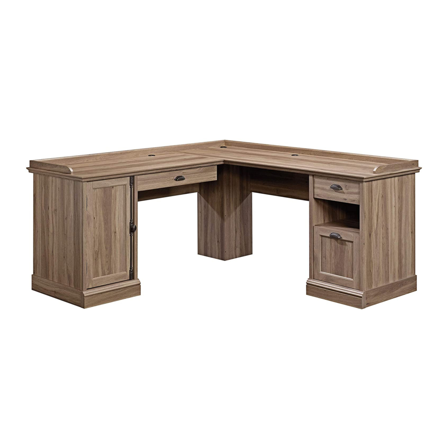
L-Shaped Desk
Barrister Lane Collection | Model 418270
Need help? Visit Sauder.com to view video assembly tips or chat with a live rep.
Prefer the phone? Call 1-800-523-3987.
Share your journey!
Business or pleasure.
Works both ways.
NOTE: THIS INSTRUCTION
BOOKLET CONTAINS IMPORTANT
SAFETY INFORMATION.
PLEASE READ AND KEEP FOR
FUTURE REFERENCE.
English pg 1-40
Français pg 41-44
Español pg 45-48
Lot # 373983
06/26/15
Purchased: __________________
Be sure to give us a ring before
making any returns. 1-800-523-3987
Publicidad
Tabla de contenido

Manuales relacionados para Sauder L-Shaped Desk


Resumen de contenidos para Sauder L-Shaped Desk
- Página 1 Barrister Lane Collection | Model 418270 NOTE: THIS INSTRUCTION BOOKLET CONTAINS IMPORTANT SAFETY INFORMATION. Need help? Visit Sauder.com to view video assembly tips or chat with a live rep. PLEASE READ AND KEEP FOR FUTURE REFERENCE. Prefer the phone? Call 1-800-523-3987.
- Página 2 D466 PENCIL DRAWER BACK (1) BACK (2) LONG LEFT MOLDING (1) D467 PENCIL DRAWER BOX FRONT (1) DOOR (1) RIGHT MOLDING (1) D716 DRAWER BOTTOM (2) ADJUSTABLE SHELF (1) LEFT MOLDING (1) BASE (2) END MOLDING (4) Page 2 418270 www.sauder.com/services...
-
Página 3: Part Identifi Cation
Part Identifi cation D109 D266 D466 D716 D716 D267 D467 www.sauder.com/services 418270 Page 3... - Página 4 KNOB - 1 PULL - 3 DECORATIVE DECORATIVE DECORATIVE NAIL - 30 POST - 2 BACKPLATE - 1 END - 2 METAL PIN - 4 RUBBER SLEEVE - 4 GROMMET CAP - 3 GROMMET - 3 Page 4 418270 www.sauder.com/services...
-
Página 5: Tabla De Contenido
BLACK 7/8" MACHINE SCREW - 2 GRAY 1-3/8" MACHINE SCREW - 2 BLACK 1-1/2" PAN HEAD SCREW - 2 GOLD 1" MACHINE SCREW - 2 BLACK 1" PAN HEAD SCREW - 8 SILVER 1-1/2" MACHINE SCREW - 1 www.sauder.com/services 418270 Page 5... - Página 6 Look for this icon. It means a Step 1 video assembly tip is available at www.sauder.com/services/tips Assemble your unit on a carpeted fl oor or on the empty å carton to avoid scratching your unit or the fl oor. Push twenty-three HIDDEN CAMS (1F) into the ENDS (A å...
- Página 7 END and UPRIGHT. Turn a SCREW into this hole. Push the black lever in and pull the SLIDE from the RAIL. Open end Notched edge GOLD 5/16" FLAT HEAD SCREW (4 used in this step) Open end Notched edge www.sauder.com/services 418270 Page 7...
- Página 8 CABINET LEFT (35GB) to the RIGHT UPRIGHT (C). Use four GOLD 5/16" FLAT HEAD SCREWS (3S) through holes #1 and #3. GOLD 5/16" FLAT HEAD SCREW Roller end (4 used in this step) Notched edge Roller end Notched edge Page 8 418270 www.sauder.com/services...
- Página 9 Tighten Risk of damage or Arrow injury. HIDDEN CAMS must be completely Arrow Maximum tightened. HIDDEN 210 degrees CAMS that are not completely tightened may loosen, and parts may separate. To Minimum completely tighten: 190 degrees www.sauder.com/services 418270 Page 9...
- Página 10 RIGHT UPRIGHT (C). Use four BLACK 1-7/8" FLAT HEAD SCREWS (2S). This hole must be here. U n fi n i s h s u r f a c BLACK 1-7/8" FLAT HEAD SCREW (4 used in this step) Page 10 418270 www.sauder.com/services...
- Página 11 S u r D E N H I D BLACK 1-7/8" FLAT HEAD SCREW (4 used in this step) www.sauder.com/services 418270 Page 11...
- Página 12 å and UPRIGHTS (C and D). Use eight BLACK 1" PAN HEAD SCREWS (60S). Long fi nished edge Long fi nished edge BLACK 1" PAN HEAD SCREW (8 used in this step) Long fi nished edge Page 12 418270 www.sauder.com/services...
-
Página 13: Black 9/16" Large Head Screw
Fasten the BASES (O) to the ENDS (A and B), UPRIGHTS (C and D), and BOTTOMS (G). Use six BLACK 9/16" LARGE å HEAD SCREWS (1S) through the METAL BRACKETS on the ENDS, UPRIGHTS, and BOTTOMS and into the BASES. Curved edge BLACK 9/16" LARGE HEAD SCREW (12 used in this step) Curved edge (6 used) www.sauder.com/services 418270 Page 13... - Página 14 Slide the END MOLDINGS (DD) onto the notched edges of the ENDS (A and B) and UPRIGHTS (C and D). å *U.S. Patent No. 5,499,886 å Slide the END MOLDINGS (DD) onto the notched edges. Notched edge Notched edge Page 14 418270 www.sauder.com/services...
- Página 15 BLACK 1-7/8" FLAT HEAD SCREW (4 used in this step) Long fl at edge Curved edge For support, place packing foam and magazines under the TOP. Flat edge Curved edge For support, place packing foam and magazines under the TOP. www.sauder.com/services 418270 Page 15...
- Página 16 Fasten a CONNECTOR PLATE (Y) to the LARGE TOP (E). Use four å SILVER 1-1/8" FLAT HEAD SCREWS (10S). Flat edge SILVER 1-1/8" FLAT HEAD SCREW (4 used in this step) Surface with more holes Packing foam Page 16 418270 www.sauder.com/services...
- Página 17 Tap two MOLDING CONNECTORS (19F) into the notches å in the MOLDINGS (Z, AA, BB, and CC). Use your hammer to tap the MOLDING CONNECTORS (19F) into the notches in the MOLDINGS. Flat end Flat end www.sauder.com/services 418270 Page 17...
- Página 18 Fasten the MOLDINGS (Z, AA, BB, and CC) to the TOPS (E and F). Use twelve SILVER 1-1/8" FLAT HEAD SCREWS (10S). å SILVER 1-1/8" FLAT HEAD SCREW (15 used in this step) Flat edge Long curved edge Packing foam Surface with more holes Packing foam Page 18 418270 www.sauder.com/services...
- Página 19 Step 14 Fasten the RIGHT END (A) and RIGHT UPRIGHT (C) to å the LARGE TOP (E) and RIGHT MOLDING (BB). Tighten Maximum Arrow 210 degrees four HIDDEN CAMS. Minimum 190 degrees Packing foam www.sauder.com/services 418270 Page 19...
- Página 20 Use two BLACK 1-7/8" FLAT HEAD SCREWS (2S). MODESTY PANEL with two HIDDEN CAMS. S u r f a c i t h H I D D E N Notch BLACK 1-7/8" FLAT HEAD SCREW (2 used in this step) Packing foam Page 20 418270 www.sauder.com/services...
- Página 21 BLACK 1-7/8" FLAT HEAD SCREWS (2S). BLACK 1-7/8" FLAT HEAD SCREW (3 used in this step) S u r f a c i t h o u t H I D D Edge with CAM DOWELS www.sauder.com/services 418270 Page 21...
- Página 22 H I D f a c e w i t h C A M D E N S u r D E N C A M H I D Packing foam Page 22 418270 www.sauder.com/services...
- Página 23 LEFT UPRIGHT (D). Use two BLACK 1-7/8" FLAT HEAD SCREWS (2S). BLACK 1-7/8" FLAT HEAD SCREW (2 used in this step) D E N H I D i t h f a c S u r Notch Packing foam www.sauder.com/services 418270 Page 23...
- Página 24 NOTE: Perforations have been provided for access through the BACK. å Carefully cut out the holes needed. Edge without holes NAIL (30 used in this step) These holes must line up over the SHELF (I). Edge without holes Page 24 418270 www.sauder.com/services...
- Página 25 HEAD SCREWS (2S) and two BLACK 1-1/2" PAN HEAD SCREWS (49S). BLACK 1-1/2" PAN HEAD SCREW BLACK 1-7/8" FLAT HEAD SCREW (2 used in this step) (10 used in this step) SILVER 1-1/8" FLAT HEAD SCREW (3 used in this step) www.sauder.com/services 418270 Page 25...
-
Página 26: Important
If you want your pencil drawer to the left, follow step 22. If you want your pencil drawer to the right, go to Step 23 now. PENCIL DRAWER ON LEFT PENCIL DRAWER ON RIGHT Page 26 418270 www.sauder.com/services... -
Página 27: Gold 5/16" Flat Head Screw
D E N C A M Roller end Finished Finished edge edge SILVER 1-1/8" FLAT HEAD SCREW GOLD 5/16" FLAT HEAD SCREW (2 used for the EXTENSION BLOCK) (4 used in this step) www.sauder.com/services 418270 Page 27... - Página 28 S u r D E N H I D Roller end Finished Finished edge edge SILVER 1-1/8" FLAT HEAD SCREW GOLD 5/16" FLAT HEAD SCREW (2 used for the EXTENSION BLOCK) (4 used in this step) Page 28 418270 www.sauder.com/services...
-
Página 29: Black 1/2" Flat Head Screw
å BLACK 1/2" FLAT HEAD SCREW (11S). NOTE: The surface of the STRIKE PLATE (6I) with å "SAUDER" should be facing up. BLACK 1/2” FLAT HEAD SCREW (1 used for the STRIKE PLATE) BLACK 9/16" LARGE HEAD SCREW (4 used for the HINGES) www.sauder.com/services... -
Página 30: Silver 5/8" Machine Screw
Push the MAGNETIC CATCH (3I) into the hole in the LONG LEFT MOLDING (AA). å SILVER 5/8" MACHINE SCREW (2 used in this step) BLACK 9/16" LARGE HEAD SCREW (4 used for the HINGES) SILVER 1-1/2" MACHINE SCREW (1 used in this step) Page 30 418270 www.sauder.com/services... -
Página 31: Black 1-9/16" Flat Head Screw
PENCIL DRAWER SIDES (D266 and D267). Use BRACE (EE) to the PENCIL DRAWER BACK (D466) and two BLACK 1-9/16" FLAT HEAD SCREWS (30S). PENCIL DRAWER BOX FRONT (D467). Use two BLACK 1-9/16" FLAT HEAD SCREWS. (30S). www.sauder.com/services 418270 Page 31... -
Página 32: Gray 1-3/8" Machine Screw
(2 used for the PULL) (2 used in this step) PENCIL DRAWER ON RIGHT Locator hole should be here. D467 GRAY 1-3/8" MACHINE SCREW BLACK 7/8" LARGE HEAD SCREW (2 used for the PULL) (2 used in this step) Page 32 418270 www.sauder.com/services... - Página 33 RIGHT SIDE (D266) and a DRAWER LEFT (35GD) to the PENCIL DRAWER LEFT SIDE (D267). Use four GOLD 5/16" FLAT HEAD SCREWS (3S) through holes #1 and #3. Roller end D267 Roller end D266 GOLD 5/16" FLAT HEAD SCREW (4 used in this step) www.sauder.com/services 418270 Page 33...
- Página 34 NOTE: Be sure the LARGE DRAWER BOTTOM (D716) inserts into the groove of the LARGE DRAWER BACK (D78). å Repeat this step for the remaining drawer using the DRAWER FRONT (R), DRAWER SIDES (D24 and D25), and å DRAWER BACK (D109). Page 34 418270 www.sauder.com/services...
- Página 35 SLIDE. Screw head - turn CAM to line up holes in the SLIDES with holes in DRAWER SIDES Open end Open end GOLD 5/16" FLAT HEAD SCREW (4 used in this step) www.sauder.com/services 418270 Page 35...
- Página 36 Screw head - turn CAM to line up holes in the SLIDES with holes in DRAWER SIDES Roller end BLACK 7/8" MACHINE SCREW (2 used for the PULLS) GOLD 5/16" FLAT HEAD SCREW (4 used in this step) Page 36 418270 www.sauder.com/services...
-
Página 37: Gold 1" Machine Screw
Use two GOLD 1" MACHINE SCREWS (50S). Almost time to Push the FILE GLIDES (4B) onto the LARGE celebrate! With a nap. å DRAWER SIDES (D14 and D15). GOLD 1" MACHINE SCREW (2 used in this step) www.sauder.com/services 418270 Page 37... - Página 38 Step 33 Insert a GROMMET (10P) and GROMMET CAP (1P) into å the large holes in the TOPS (E and F). Page 38 418270 www.sauder.com/services...
- Página 39 The drawer will push in hard until it is all the way in, then it will slide in and out easier. 60 lbs. 20 lbs. 40 lbs. 5 lbs. 10 lbs. 30 lbs. 30 lbs. (4 used) 40 lbs. www.sauder.com/services 418270 Page 39...
- Página 40 #3. The higher the screw in the oblong hole, the higher your drawer front will be. The lower the screw, the lower the drawer front. Page 40 418270 www.sauder.com/services...
-
Página 41: Liste De Pièces
EXTRÉMITÉ GAUCHE ................ 1 GLISSIÈRE D'EXTENSION ..............2 MONTANT DROIT ................. 1 COULISSE D'EXTENSION..............2 Pour contacter Sauder MONTANT GAUCHE ................1 35GA ÉLÉMENT DROITE ................2 en ce qui concerne cet GRAND DESSUS ..................1 35GB ÉLÉMENT GAUCHE ................2 élément, faire référence... - Página 42 Fixer les PLINTHES LATÉRALES (P) aux EXTRÉMITÉS (A et B) et MONTANTS (C et D). Utiliser huit VIS TÊTE GOUTTE DE SUIF 25 mm NOIRES (60S). ÉTAPE 16 Fixer l'ARRIÈRE DROIT (J) à l’ARRIÈRE GAUCHE (K). Utiliser trois VIS TÊTE PLATE 48 mm NOIRES (2S). Page 42 418270 www.sauder.com/services...
- Página 43 EXCENTRIQUE ESCAMOTABLE. REMARQUE : La surface de la PLAQUE DE BUTÉE (6I) comportant l'inscription « SAUDER » devrait être dirigée vers le haut. Fixer les TRAVERSES (U et V) au les DESSUS (E et F). Utiliser huit VIS TÊTE PLATE 48 mm NOIRES (2S) et deux VIS TÊTE GOUTTE DE SUIF 38 mm NOIRES (49S).
- Página 44 Ceci complète l'assemblage. Nettoyer à l’ a ide d’une encaustique pour meubles ou d’un chiff on humide. Essuyer. REMARQUE : La tête de vis dans l'EXCENTRIQUE doit être visible à travers le trou fendu dans la COULISSE. Page 44 418270 www.sauder.com/services...
-
Página 45: Escritorio En Forma De L
PARAL DERECHO ................. 1 pour future référence. CORREDERA DE EXTENSIÓN ............2 PARAL IZQUIERDO ................1 35GA GABINETE DERECHO ...............2 Pour contacter Sauder PANEL SUPERIOR GRANDE ............1 35GB GABINETE IZQUIERDO ..............2 en ce qui concerne cet PANEL SUPERIOR PEQUEÑO ............. 1 35GC CAJÓN DERECHO ................2... - Página 46 NEGROS DE CABEZA PERDIDA de 48 mm (2S). Fije los FALDONES LATERALES (P) a los EXTREMOS (A y B) y a los PARALES (C y D). Utilice ocho TORNILLOS NEGROS DE CABEZA REDONDA de 25 mm (60S). Page 46 418270 www.sauder.com/services...
- Página 47 NEGRO DE CABEZA PERDIDA de 13 mm (11S). Fije el VELO DE FONDO (H) al DORSO IZQUIERDO (K). Utilice dos TORNILLOS NOTA: La superfi cie de la PLACA DE CONTACTO (6I) con la inscripción "SAUDER" NEGROS DE CABEZA PERDIDA de 48 mm (2S).
- Página 48 Seque con un paño. PERDIDA de 8 mm (3S) a través de los agujeros No. 1 y No. 3. NOTA: La cabeza de tornillo del EXCÉNTRICO debe ser visible a través del agujero alargado de la CORREDERA. Page 48 418270 www.sauder.com/services...
- Página 49 à Les téléviseurs peuvent être particulièrement un téléviseur. cet eff et. lourds. De plus, le poids et l’emplacement du tube image ont tendance à rendre les téléviseurs instables et enclins à tomber vers l’ a vant. www.sauder.com/services 418270 Page 49...
- Página 50 Además, el peso y la ubicación del tubo de imagen tienden a causar la inestabilidad de televisores y propensa a volcarse hacia adelante. Page 50 418270 www.sauder.com/services...
-
Página 51: Garantie Limitée De 5 Ans
à compter de la date d'achat la première fois et qui sont signalés à Sauder dans les limites de couverture de la contre tout défaut de matériaux ou de fabrication des composantes de mobilier Sauder. - Página 52 Dear Valued Customer: So, how did it go? Thanks so much for choosing Sauder® furniture. I hope the Set a world record for speed? purchase and assembly process was a positive experience Feeling good about yourself? and you feel good about the furniture you just built. If you Nice.