Publicidad
Enlaces rápidos
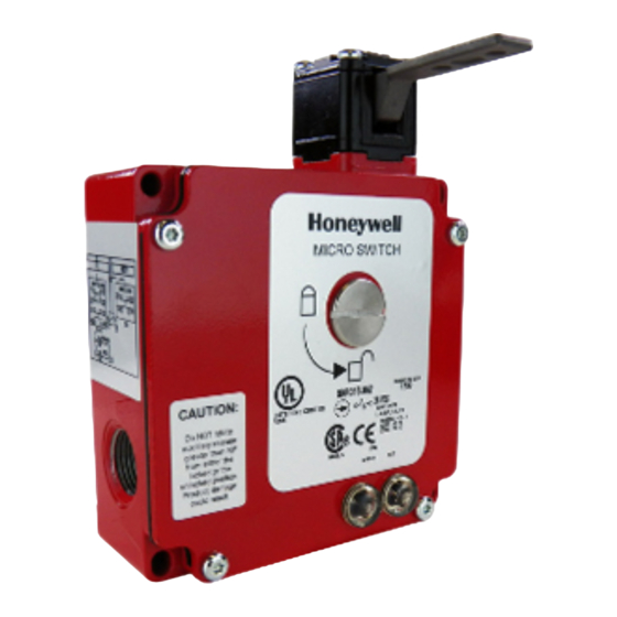
Installation Instructions for the Dual Entry Solenoid Key Operated Safety Interlock Switch (GKR/GKL Series)
Instrucciones de instalación para interruptores de seguridad de solenoide con llave de doble entrada (serie GKR/GKL)
Einbauanweisungen für den Doppeleingangs-Sicherheits-Verriegelungsschalter mit separatem Betätiger und
Magnetspule (Serie GKR/GKL)
Instructions d'installation de l'interrupteur de sécurité avec interverrouillage à Istruzioni per l'installazione
dell'interruttore con interblocco di sicurezza azionato a chiave a solenoide a doppio ingresso (Serie GKR/GKL)
Instruções de Instalação para o Switch de Bloqueio de Segurança Operado por Chave com Solenóide de Duas En-
tradas (Séries GKR/GKL)
이중 입구 솔레노이드 키 동작 안전 인터록스위치 (GKR/GKL 시리즈) 설치 설명서
m
WARNING
IMPROPER INSTALLATION
• Consult with local safety agencies and their requirements
when designing a machine-control link, interface, and all
control elements that affect safety.
• Strictly adhere to all installation instructions.
Failure to comply with these instructions could result in
death or serious injury.
MOUNT, WIRE, SEAL, AND TEST SWITCH
m
WARNING
IMPROPER OPERATION
• Ensure key travels to the given minimum insertion
distance to ensure switch contact transfer.
• Ensure key travels to maximum extraction distance to
ensure correct operation of the positive break mechanism.
• Do not exceed 100 N (22.4 lb) actuation force or 1000 N
(224 lb) extraction force to actuator key to prevent switch
failure.
• Do not use the key as a stop for the door.
Failure to comply with these instructions could result in
death or serious injury.
1.
Refer to:
•
Page 11 for wiring configurations for both lock types.
•
Page 13 for switch mounting dimensions,
specifications.
•
Page 14 for key mounting dimensions.
2.
Rotate head (if desired):
•
Rotate the auxiliary release to the unlocked position
(requires cover to be in place).
•
Using the TORX® tamper resistant bit (included),
loosen tamper-proof screws and remove head.
•
Rotate head to desired position (90 increments),
ensuring seal and plunger remain in correct position
while reassembling head.
•
Torque tamper-proof screws 1,36 Nm to 1,80 Nm (12
in-lb to 16 in lb).
•
Return auxiliary release to the locked position.
Sensing and Internet of Things
3.
Ensure proper clearance for switch and key at mounting
location.
4.
Align switch and key together before mounting.
5.
Mount switch and key:
•
Torque switch to mounting surface: 4,9 Nm to 5,9 Nm
(43 in-lb to 52 in-lb) using M5 or #10 screws.
•
Torque key to mounting surface: 4-2,8 N m (21in-lb to
25 in-lb) using M5 or #10 screws.
6.
Refer to circuit diagram on switch housing. Diagram
depicts safety switch when key is inserted.
7.
Remove tamper-proof screws on cover plate.
8.
Connect stranded wire (0,75 mm
AWG) or solid wire (0,75 mm
to connector terminals (use 90 °C wire when ambient
temperature is over 75 °C):
•
Torque connector to secure cable to switch enclosure
(if required): 1,8 Nm to 2,2 Nm (16 in-lb to 19 in-lb).
•
Torque switch terminal screws: 0,8 Nm to 1,0 Nm (7
in-lb to 9 in-lb) M3.
•
Torque ground screw: 0,8 Nm to 1,0 Nm (7 in-lb to 9
in-lb) M3.
9.
Seal conduit opening according to instructions in PK
80112.
10. Reassemble cover plate.
11. Plug unused conduit entry (plug included). Seal with
Teflon tape or pipe sealant.
12. Plug unused key entry window with snap fit cover
(included).
13. Perform functional tests:
•
Open and close protective guard several times to
ensure key slides easily into switch head.
•
Close protective guard and ensure switch locks. It
must not be possible to open protective guard when
hazardous motion is present.
•
After the switch unlocks, open protective guard. The
hazardous motion must not start when protective
guard is unlocked or open.
14. Apply a strip of paint or wax over the auxiliary release
knob and the switch body cover to detect actuation of the
auxiliary release.
Issue 13
80108
to 2,5 mm
, 18-14
2
2
to 1,5 mm
, 18-16 AWG)
2
2
Publicidad

Manuales relacionados para Honeywell GKR Serie


Resumen de contenidos para Honeywell GKR Serie
- Página 1 Issue 13 80108 Installation Instructions for the Dual Entry Solenoid Key Operated Safety Interlock Switch (GKR/GKL Series) Instrucciones de instalación para interruptores de seguridad de solenoide con llave de doble entrada (serie GKR/GKL) Einbauanweisungen für den Doppeleingangs-Sicherheits-Verriegelungsschalter mit separatem Betätiger und Magnetspule (Serie GKR/GKL) Instructions d’installation de l’interrupteur de sécurité...
- Página 2 Vuelva a dejar el dispositivo auxiliar de liberación en la posición de traba. Asegúrese que exista la separación adecuada para el interruptor y la llave en el lugar de montaje. Alinee el interruptor y la llave juntos antes de montarlos. 2 sensing.honeywell.com...
- Página 3 MICRO SWITCH GKL/GKR Series PK 80108 ISSUE 13 Monte el interruptor y la llave: PRECAUCIÓN • Ajuste el interruptor a la superficie de montaje: DAÑOS AL PRODUCTO 4,9 Nm a 5,9 Nm (43 pulg-lb a 52 pulg-lb) usando tornillos M5 o del número 10. •...
- Página 4 Magnetspule, wird die Schutzvorrichtung entriegelt. 11. Den mitgelieferten Blindstopfen für die unbenutzte Kabeleinführung verwenden. Mit Teflonband oder Die Hilfsentriegelung des Verriegelungsmechanismus Rohrdichtungsmasse abdichten. ermöglicht das Öffnen der Schutzvorrichtung. Die Zeichnung auf der Schalterabdeckplatte zeigt die korrekte Drehrichtung 4 sensing.honeywell.com...
- Página 5 MICRO SWITCH GKL/GKR Series PK 80108 ISSUE 13 Montage de l’interrupteur et de la clé: AVERTISSEMENT • Serrez l’interrupteur sur la surface de montage avec un INSTALLATION INCORRECTE couple de 4,9 N.m à 5,9 N.m (43 in.lb à 52 in.lb) à l’aide •...
- Página 6 Serrare le viti a prova di manomissione ad una coppia di 1,36-1,80 N m (12-16 poll. lb). • Riportare lo sblocco ausiliario in posizione di blocco. Garantire la presenza di un adeguato spazio libero per l’interruttore e la chiave in corrispondenza della sede di montaggio. 6 sensing.honeywell.com...
- Página 7 MICRO SWITCH GKL/GKR Series PK 80108 ISSUE 13 Prima del montaggio, allineare l’interruttore e la chiave. SBLOCCO AUSILIARIO Montare l’interruttore e la chiave: ATTENZIONE • Serrare l’interruttore sulla superficie di montaggio alla FUNZIONAMENTO SCORRETTO coppia: 4,9 Nm - 5,9 Nm (43 poll. lb - 52 poll. lb) con viti M5 o #10.
- Página 8 Aperte os parafusos invioláveis com um torque de 1,36 N-m - 1,80 N-m (30,48 cm-lb - 40,64 cm-lb). • Gire a liberação auxiliar de volta à posição travada. Certifique-se de que haja espaço apropriado para o switch e a chave no local de montagem. 8 sensing.honeywell.com...
- Página 9 MICRO SWITCH GKL/GKR Series PK 80108 ISSUE 13 LIBERAÇÃO AUXILIAR 경고 ADVERTÊNCIA 부적절한 설치 INSTALAÇÃO INCORRETA • 기계 제어 링크, 인터페이스 및 기타 안전에 영향을 주는 • NÃO use a liberação auxiliar para prestar manutenção 모든 제어 요소를 설계할 때는 지역 안전 관리 기관에 geral, reparar a máquina ou ligar e desligar a máquina.
- Página 10 솔레노이드 잠금: 기계 안전 가드를 닫고 키를 삽입한 후 솔레노이드에 전압을 가하면 작동됩니다. 솔레노이드에 전압을 가하면 안전 가드가 잠금 해제됩니다. 스위치 잠금 장치의 보조 해제를 통해 안전 가드를 열 수 있습니다. 적절한 회전 방향에 대해서는 스위치커버의 그림을 참조하십시오. 10 sensing.honeywell.com...
- Página 11 MICRO SWITCH GKL/GKR Series PK 80108 ISSUE 13 Mechanical Lock Circuitry: Protective guard closed and locked Circuitos de la traba mecánica: Barrera protectora cerrada y trabada Schaltkreis der mechanischen Verriegelung: Schutzvorrichtung geschlossen und verriegelt Circuit de verrouillage mécanique: Protecteur fermé et verrouillé Circuito di bloccaggio meccanico: Riparo di protezione chiuso e bloccato Circuito da Trava Mecânica: Guarda protetora fechada e travada 기계적...
- Página 12 2. 빨간색 LED 2. LED vermelho 2. LED rouge 2. LED rosso 3. LED 공통 3. LED comum 3. LED commun 3. comune LED 4. 솔레노이드 4. Solenóide 4. Electro-aimant 4. Elettromagnete 5. 솔레노이드 5. Solenóide 5. Electro-aimant 5. Elettromagnete 12 sensing.honeywell.com...
- Página 13 MICRO SWITCH GKL/GKR Series PK 80108 ISSUE 13 Designation and Rated Operational Current Ie (A) at Rated Operational Voltage Ue (V) Utilization Category 24 V 120 V 240 V AC15 A300 DC13 Q300 2,8 A 0,55 A 0,27 A Rated Thermal Current (Ith) 10 A Rated Impulse Withstand (Uimp) 2500 V...
- Página 14 Distância máxima de inserção 최대 삽입 거리 Rayon de pivotement minimum Raggio di deviazione minimo Raio mínimo de oscilação 최소 선회 반경 Vis de réglage du pivotement Vite di regolazione deviazione Parafuso de ajuste da oscilação 선회 조정 나사 14 sensing.honeywell.com...
- Página 15 If warranted goods are returned to Honeywell during défauts matériels et de fabrication, et ce pendant la période de the period of coverage, Honeywell will repair or replace, at its option, garantie applicable. Sauf indication contraire écrite et approuvée par without charge those items that Honeywell, in its sole discretion, Honeywell, la garantie standard sur les produits Honeywell s’applique.
- Página 16 A Honeywell garante seus produtos contra defeitos de material e de fabricação durante o período de garantia aplicável. A garantia padrão de produto da Honeywell se aplica a menos que haja um acordo diferente com a Honeywell por escrito. Consulte a confirmação do seu pedido ou procure o escritório local de vendas para obter detalhes...