Publicidad
Idiomas disponibles
Idiomas disponibles
Enlaces rápidos
Installation
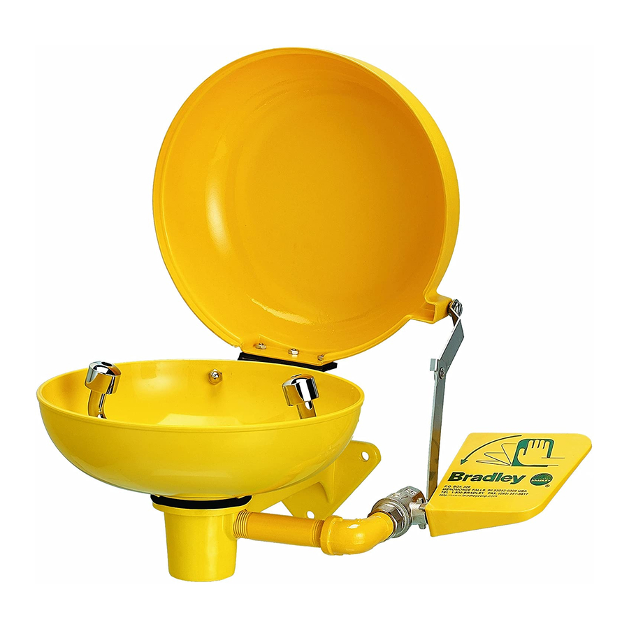
To attach Plastic Dust Cover to existing unit:
NOTE: For clarity, only the bowl, handle and ball valve from the existing eyewash unit are shown in
the illustration. Refer to the installation manual provided with the eyewash unit (if available) for
eyewash assembly information.
NOTE: Main water supply to the unit should be turned off before beginning installation.
1. Detach the flag handle from the
ball valve.
2. Turn the eyewash assembly
approximately 360° to loosen the
assembly from the bowl and allow
the bowl to move freely.
3. Position the dust cover assembly
on top of the eyewash bowl.
4. Using the holes in the dust cover
bracket as a template, drill two
1/4" holes in the eyewash bowl.
5. Attach the dust cover to the bowl
with the 1/4" screws and secure
the cover with the 1/4" acorn nuts
(hardware provided by Bradley).
6. If necessary, rotate the eyewash
bowl so that the dust cover's
hinge bracket is positioned at the
rear of the unit.
7. Retighten the eyewash assembly
to the bowl by rotating it
approximately 360°.
8. Install the stop bracket on the ball
valve.
NOTE: Bracket tabs must face ball
valve and be oriented 180° from the
stops on the flag handle.
9. Attach the dust cover linkage to
the handle stem and reattach the
flag handle.
10. Turn on the water supply and
check for leaks and adequate
water flow.
215-1435 Rev. D; EN 07-520
© 2007 Bradley Corporation
Page 1 of 3
8/27/07
S45-1964
Dust Cover Retrofit Kit
DUST COVER
(154-140)
SCREW (160-444)
HEX NUT (161-062)
UTILITY HINGE
(220-128)
1/4-20 SCREW
(160-389)
BRACKET
(140-910)
EYEWASH
P.O. Box 309, Menomonee Falls, WI 53052-0309
Phone: 1-800-BRADLEY Fax: (262) 251-5817
http:\\www.bradleycorp.com
SCREW (160-310)
JAM NUT (161-060)
HEX NUT (161-078)
1/4-20 ACORN
NUT (161-052)
BALL
STOP BRACKET
VALVE
LINK
ASSEMBLY
(S70-170)
FLAG
HANDLE
(140-695)
Publicidad

Manuales relacionados para Bradley S45-1964


Resumen de contenidos para Bradley S45-1964
- Página 1 10. Turn on the water supply and check for leaks and adequate water flow. 215-1435 Rev. D; EN 07-520 P.O. Box 309, Menomonee Falls, WI 53052-0309 Phone: 1-800-BRADLEY Fax: (262) 251-5817 © 2007 Bradley Corporation http:\\www.bradleycorp.com Page 1 of 3 8/27/07...
- Página 2 à la tige de la poignée et rattacher la poignée. 10. Ouvrez l’alimentation en eau. Assurez-vous que le débit d’eau est adéquat et qu’il n’y a pas de fuites . 8/27/07 Bradley Corporation • 215-1435 Rev. D; EN 07-520...
- Página 3 10. Abrir las líneas del suministro de agua. Verificar que no haya fugas y que el flujo de agua sea adecuado. Bradley Corporation • 215-1435 Rev. D; EN 07-520 8/27/07...