Graf 230010 Instrucciones De Instalación Y Mantenimiento
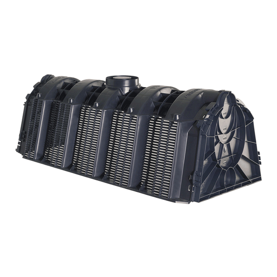
Túnel de infiltración
Ocultar thumbs
Ver también para 230010:
- Instrucciones de instalación y mantenimiento (6 páginas) ,
- Instrucciones de installación (28 páginas)
Tabla de contenido
Publicidad
Idiomas disponibles
Idiomas disponibles
Enlaces rápidos
SICKER-TUNNEL / TWIN
DE
Anleitung für Einbau und Wartung
GRAF Sicker-Tunnel / Sicker-Tunnel twin
>> Seite 1-6
EN
Installation and maintenance instructions for
GRAF Infiltration tunnel / Infiltration tunnel twin
>> Page 7-12
ES
Instrucciones de instalación y mantenimiento
Túnel de infiltración / Túnel de infiltratión twin
>> Página 13-18
FR
Notice d'Installation Tunnel d'épandage GRAF + Tunnel Twin
>> Page 19-25
Publicidad
Capítulos
Tabla de contenido

Manuales relacionados para Graf 230010


Resumen de contenidos para Graf 230010
- Página 1 Installation and maintenance instructions for GRAF Infiltration tunnel / Infiltration tunnel twin >> Page 7-12 Instrucciones de instalación y mantenimiento Túnel de infiltración / Túnel de infiltratión twin >> Página 13-18 Notice d’Installation Tunnel d’épandage GRAF + Tunnel Twin >> Page 19-25...
-
Página 2: Tabla De Contenido
Anleitung für Einbau und Wartung GRAF Sicker-Tunnel/ Sicker-Tunnel twin SICKER-TUNNEL 300 L, schwarz, LKW-befahrbar Best.-Nr. 230010 SICKER-TUNNEL TWIN 600 L, schwarz, PKW-befahrbar Best.-Nr. 410130 SICKER-TUNNEL Endplatte 300 L Best.-Nr. 231004 Zubehör: Verbindungselemente (6 Stck) Best.-Nr. 410094 Geotextil (lfm, Rollenbr. 5 m) Best.-Nr. -
Página 3: Allgemeine Hinweise
Allgemeine Hinweise Sicherheit Bei sämtlichen Arbeiten sind die einschlägigen Unfallverhütungsvorschriften nach BGV C22 zu beachten. Des Weiteren sind bei Einbau, Montage, Wartung, Reparatur usw. die in Frage kommenden Vorschriften und Normen zu berücksichtigen. Vor dem Einbau sind die Rigolenelemente auf Beschädigungen zu überprüfen. Beschädigte oder fehlerhafte Tunnel dürfen nicht eingebaut werden! -
Página 4: Technische Daten
Technische Daten 1160 incl. Endplatte 1220 mm 1020 DN 100 DN 200 DN 100 DN 150 DN 200 DN 300 DN 100 Einbaubedingungen Standortwahl Abstand zum Keller > 6 m Abstand zum Grundwasser mindestens 1 m Der Abstand zum bestehenden oder geplanten Baumbestand muss mindestens dem zu erwartenden Kronendurchmesser entsprechen. -
Página 5: Abmessungen Der Baugrube
Einbaubedingungen Abmessungen der Baugrube Die Abmessung der Grube richtet sich nach der Anzahl der zu verlegenden Sickertunnel in Längs- und in Querrichtung. Die nachfolgende Tabelle gibt die Erdüberdeckung und die maximale Einbautiefe bis Unterkante der Rigole an: Verkehrsbelastung... -
Página 6: Einbau
Einbau Anschluss der Zu- und Entlüftungsleitungen Die Zuleitungen werden an den Stirnseiten an den Endplatten angeschlossen. Dazu werden die entsprechend perforierten und beschrifteten Kreisausschnitte herausgetrennt. Die Leitungen müssen ca. 15 cm in die Module hineinragen. Um einen gleichmäßigen Wassereintritt zu gewährleisten ist bei einer flächenhaften Verlegung der Module eine Verteilung der Zuleitungen auf jeden Versickerungsstrang... - Página 7 Einbau Schnittdarstellung – SLW 60 Belastungsfall: Schnittdarstellung offene Mulden-Rigole: 6 / 25 2015-07...
- Página 8 Installation and maintenance instructions GRAF Infiltration tunnel / Infiltration tunnel Twin Infiltration tunnel 300 L, black, lorry loading Order No. 230010 Infiltration tunnel Twin 600 L, black, vehicle loading Order No. 410130 End plate for Infiltration Tunnel /Twin Order No.
-
Página 9: General Notes
Damaged or defective blocks must not be installed! GRAF offers an extensive range of accessories, all of which are designed to match each other and which can be extended to form complete systems. The use of other accessories may lead to impediments to the system's functional capability, therefore invalidating liability for resulting damage. -
Página 10: Installation Conditions
Installation conditions Choice of location Distance from basement > 6 m Distance from ground water minimum > 1 m The distance from the existing or planned trees must be at least the expected spread of the trees crown. - Página 11 Installation conditions Technical data Infiltration Tunnel Infiltration Tunnel Twin Volume Litre 300 L 600 L Weight 11 kg 22 kg Material 100 % polypropylene (PP)° 100 % polypropylene (PP)° Length excl. Endplatten 1160 mm 1160 mm Length incl. Endplatten...
-
Página 12: Installation
Installation Connecting the inlet and venting pipes The feed pipes will be connected at the front of the end plates. For this purpose the accordingly perforated and labelled circular cut-outs will be detached. The feed pipes must extend into the tunnel modules approximately 15 cm. - Página 13 20/40 soil 80-100 mm grit (8/16) granular subbase angle of slope 45° Section open swale infiltration ditch: road/ parking space GRAF-Tex geotextile max. 250 – 3740 mm filling material infiltration Tunnel 12 / 25 2015-07...
- Página 14 Elección de la ubicación separado las instrucciones de Dimensiones de la excavación montaje para todos los artículos adicionales adquiridos a GRAF. INSTALACION Conexión de los tubos de entrada y de aireación Antes de trasladar los Instalación del túnel de infiltración / Twin componentes a la excavación...
-
Página 15: Indicaciones Generales
Indicaciones generales Sicherheit En la ejecución de todos los trabajos deben seguirse las prescripciones pertinentes de prevención de accidentes según BGV C22. Aparte de esto se deben seguir las prescripciones y normas correspondientes para la ejecución de los trabajos de instalación, montaje, mantenimiento, reparación, etc. -
Página 16: Datos Tecnicos
Datos técnicos 1160 Incl. placa final 1220 mm incl. Endplatte 1220 mm 1020 DN 100 DN 200 DN 100 DN 150 DN 200 DN 300 DN 100 Conditiones para la instalación Elección de la ubicación Distancia respecto a edificios > 6 m Distancia a las aguas subterráneas: mínimo 1 m... -
Página 17: Dimensiones De La Excavación
Conditiones para la instalación Dimensiones de la excavación Las dimensiones de la excavación se orientarán en la cantidad de túneles de infiltración a instalar en sentido longitudinal y transversal. La tabla siguiente indica la capa de cobertura con tierra y la profundidad máxima de instalación hasta el canto inferior del módulo de infiltración:... -
Página 18: Instalacion
Instalación Conexión de los tubos de entrada y de aireación Los tubos de entrada se conectan en las placas finales. Con este fin hay que cortar las piezas circulares pre-perforadas y rotuladas. Los tubos tienen que entrar aprox. 15 cm dentro de los módulos. En el caso de una instalación de varias filas de túneles habrá... - Página 19 Instalación Vista en sección – Supuesto de carga "Camiones de hasta 60t": 18 / 25 2016-02...
- Página 20 Notice d’installation Tunnel d’épandage GRAF + Tunnel Twin Tunnel d’épandage Graf 300 L – passage ≤ 3,5 T Réf: 410090 Tunnel Twin 600 L – passage ≤ 3,5 T Réf: 410130 Paroi d’entrée/sortie (1 pc.) pour Tunnel (2) / Twin (4) Réf: 410091...
-
Página 21: Indications Generales
L’installation, le montage, l’entretien et la réparation des matériels concernés qui doivent être réali- sés conformément aux normes et prescriptions en vigueur.. N’utiliser que des accessoire de marque GRAF. L’utilisation d’autres accessoires pourrait ne pas être adaptée et engendrer des problèmes tels que fuites. -
Página 22: Conditions D'INstallation
Données techniques Tunnel Tunnel Twin Litres 300 L 600 L Longueur hors paroi d’entrée/sortie 1160 mm 1160 mm Longueur avec paroi d’entrée/sortie 1200 mm 1200 mm Largeur 800 mm, 800 mm Hauteur 510 mm 1020 mm Poids 11 kg 22 kg Matériau... -
Página 23: Dimensions De La Fouille Pour Tunnels
Dimensions de la fouille pour tunnels Le tableau ci-dessous donne la hauteur de recouvrement ainsi que la profondeur d’enfouissement maximale, fonction nature terrain. Passage PL (Max.12 Piétons (Max.2.5 T) (Max.30 T) (Max.40 T) (Max.60 T) Hauteur de remblai minimale Avec un angle de frottement interne φ´=25°... -
Página 24: Dimensions De La Fouille Pour Tunnels Twin
Dimensions de la fouille pour tunnels Twin Charges admises Tunnel Twin A court terme max. 7,5 t/m² Long terme max. 3,5 t/m² Recouvrement min. 250 mm Sans passage Recouvrement max. 1480 mm véhicules Profondeur 2500 mm d’enfouissement max. - Página 25 Vue du dessus : Chaussée Remblai Géo-grille (facultatif) Remblai : mélange de terre végétale et de sable Géotextile 200g/m2 Regard d’inspection DN 110 / DN 200 Gravier (8/16) Tunnel d’épandage 300 Tuyau d’arrivée Ø max. DN 300 Canal de distribution...
- Página 26 Schéma de principe Geogrille (facultatif) Regard dd’inspection/ évent Remblai Geotextile Min. 500 mm Tunnel Coupe d’une tranchée d’infiltration Géotextile 250-3740 mm max. Remblai Hauteur de remblai Tunnel 25 / 25 2016-02...
- Página 27 Notizen / Notes / Notas...
- Página 28 © Otto Graf GmbH/963184...