Tabla de contenido
Publicidad
Idiomas disponibles
Idiomas disponibles
Enlaces rápidos
BEFORE YOU START
BEFORE INSTALLING PUMP, BE SURE TO READ
THIS OWNER'S MANUAL CAREFULLY.
REFER TO PRODUCT DATA PLATE(S) FOR
ADDITIONAL OPERATING INSTRUCTIONS AND
SPECIFICATIONS.
C A U T I O N
• Keep work area clean, well-lit and uncluttered.
• Keep safety labels clean and in good condition.
• Replace missing or damaged safety labels.
• Wear safety glasses while installing or performing
maintenance on pump.
• Adhere to the guidelines of the National Electric Code
(NEC) or Canadian Electric Code (CEC), and any other
state and local codes for ALL electrical installations.
Check with the appropriate agencies or contact a
licensed electrician.
Most water system problems result from improper
installation. It is suggested that you read this
manual carefully before installing your pump. The
"TROUBLESHOOTING SECTION" will assist you in
locating and eliminating the cause of any trouble you
may encounter after installation. Check and make
available all the tools you will need to install your pump.
Required tools may include wrenches, pipe sealant, pipe
fi ttings and nipples, screwdriver, etc.
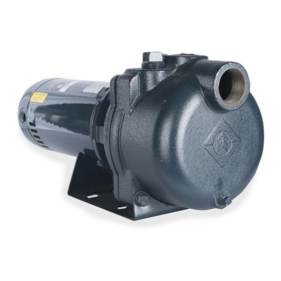
Self Priming Sprinkler Pump
OWNER'S MANUAL
Be sure to have available proper and adequate wiring
material to complete the installation correctly.
READ AND FOLLOW SAFETY INSTRUCTIONS
This is the safety alert symbol. When you see
this symbol on your pump or in this manual, look
for one of the following signal words and be alert to the
potential for personal injury:
warns about hazards that
D A N G E R
serious personal injury, death or major property damage
if ignored.
warns about hazards that can cause
W A R N I N G
serious personal injury, death or major property damage
if ignored.
warns about hazards that will or can
C A U T I O N
cause minor personal injury or major property damage if
ignored.
NOTICE indicates special instructions, which are
important but not related to hazards.
Carefully read and follow all safety instructions in
this manual and on pump.
WA R N I N G
W A R N I N G
HAZARDOUS PRESSURE: Do not run
pump against closed discharge. Release all system
pressure before working on any component.
C A U T I O N
Do not run pump dry. Fill pump with
water before starting or pump will be damaged.
The motor on this pump is guaranteed by the
manufacturer and in event of failure it must be returned
to an authorized service station for repairs. Motor
warranty is void if repairs aren't made by an authorized
repair station.
will
cause
WA R N I N G
Publicidad
Tabla de contenido

Manuales relacionados para Franklin Electric TB15CI


Resumen de contenidos para Franklin Electric TB15CI
- Página 1 Self Priming Sprinkler Pump OWNER'S MANUAL Be sure to have available proper and adequate wiring material to complete the installation correctly. READ AND FOLLOW SAFETY INSTRUCTIONS This is the safety alert symbol. When you see this symbol on your pump or in this manual, look for one of the following signal words and be alert to the potential for personal injury: will...
-
Página 3: Electrical Safety
ELECTRICAL SAFETY INTRODUCTION Make sure all ELECTRICAL POWER IS You have purchased one of the most user friendly C A U T I O N OFF before connecting any electrical wires. pumps available. The Turf Boss pumps are made with high quality materials which are designed to provide Capacitor voltage may be hazardous. -
Página 4: Pre-Installation Check
• OUTDOOR PUMP INSTALLATION OPTION: PRE-INSTALLATION CHECK When installing outside of the house, the pump should • Pump must not be more than 25 feet above the be protected by a pump house with auxiliary heat to surface of the water. prevent possible freezing. - Página 5 PLUMBING Multi-shallow Well Points (Figure 2) Bolt the pump to a level, solid foundation, if possible. The multi-point shallow well confi guration consists of Position the pump with the suction port facing the two or more wells as a water supply. The wells should water source pipe(s).
- Página 6 A. Suction Port Connection (Figure 4) B. Discharge Port Connections (Figure 5) Step 1: Step 1: Thread male adapter or pipe nipple into discharge port Attach the foot valve or well point to pipe assembly on top of pump. (Use tefl on tape on thread) and lower pipe and foot valve until it is at least fi...
-
Página 7: Electrical Installation
INSTALLATION RECORDS DUAL VOLTAGE ADJUSTMENT To keep an accurate record of your installation, be NOTE: To change the motor voltage(Figure 6) unplug sure to fi ll out the data below: the dual voltage connector on the motor and reconnect it in the position required to match the available Date of Installation: electrical system. - Página 8 Step 4: Step 3: Replace priming port plug and tighten with wrench, Connect the incoming power supply wires to the using tefl on tape on pipe threads. motor terminal. Step 5: Step 4: Start the pump. A properly primed pump should Replace and secure motor cover.
-
Página 9: Pump Assembly
to insure a proper fi t. Place the shaft seal on the motor Figure 8 shaft and then install the impeller and eye-seal. The Priming Port diffuser is positioned by three bolts that can only be installed when the diffuser is oriented properly (Figure 9). - Página 10 1 1I 9F,G 8E,G 6E,G 4C,G 7E,G 3C,G Repair Part Order Codes by Model Number Figure Kit Grouping Description Number Identifi er* TB1CI TB15CI TB2CI Plug Kits 305390901 Pump Case 305491901 305392901 Grommet 305396901 305396902 305396903 305392901 Diaphragm 305396901 305396902...
- Página 11 APPENDIX II - TROUBLESHOOTING A. Pump does not deliver water or pressure E. Motor will not start Cause: The pump is not full of water. Cause: Open switches, blown fuses or loose connections. Remedy: Stop the pump, fi ll it with water, check all pipe connections to make sure there are no air leaks Remedy: Check switches, fuses, and connections.
- Página 12 APPENDIX III - PERFORMANCE CURVE 2 HP 1.5 HP 1 HP M PH...
- Página 13 APPENDIX IV - FRICTION LOSS TABLES 1¼” 1” Schedule 40 pipe 1.049 in. i.d. / Type L Copper tube 1.025 in. i.d. Schedule 40 pipe 1.380 in. i.d. / Type L Copper tube 1.265 in. i.d. Friction Loss Friction Loss Ft Hd./ Ft Hd./ Ft Hd./100’...
- Página 14 Franklin Electric Co., Inc. Franklin Electric Co., Inc. warrants its new products to be free of defects in material and workmanship for a period of 1 year from date of installation or 2 years from date of manufacture, whichever comes fi rst, WHEN installed in clean, potable water applications.
-
Página 15: Bomba Para Regadores Autocebante
Bomba para regadores autocebante MANUAL DEL PROPIETARIO Cerciórese de tener a disposición material adequado y apropiado para el cableado para concluir la instalación correctamente. LEA Y SIGA LAS INSTRUCCIONES DE SEGURIDAD Éste es un símbolo de alerta de seguridad. Cuando usted vea este símbolo en su bomba o en este manual, busque una de las palabras siguientes y esté... -
Página 17: Seguridad Eléctrica
SEGURIDAD ELÉCTRICA INTRODUCCIÓN CUIDADO Usted ha comprado una de las bombas de manejo Cerciórese que todas las FUENTES más amigable que existen. Las bombas TurfBoss se ELÉCTRICAS ESTÉN APAGADAS antes de conectar fabrican con materiales de alta calidad diseñados para cualquier cable eléctrico. -
Página 18: Verificación Antes De La Instalación
VERIFICACIÓN ANTES DE LA INSTALACIÓN • OPCIÓN DE INSTALACIÓN DE BOMBA EXTERNA: Cuando se instale fuera de la casa, la bomba se debe • La bomba no debe de estar a más de 25 pies sobre proteger con un alojamiento con calor auxiliar para la superfi... -
Página 19: Tubería De Succión De Desvío Horizontal
TUBERÍAS Puntos de Múltiples Pozos llanos (Figura 2) La confi guración pozo llano de múltiples puntos Atornillar la bomba a una base nivelada y sólida, si consiste en dos o tres pozos como fuente de agua. es posible. Ubicar la bomba con el bocal de succión Los pozos deben estar por lo menos a cinco pies de de frente para el(los) caño(s) de la fuente de agua. - Página 20 A. Conexión del Bocal de Succión (Figura 4) B. Conexiones del Bocal de Salida (Figura 5) Etapa 1: Etapa 1: Conectar la válvula de pedestal o el punto del pozo Enroscar el adaptador macho o el niple del tubo al bocal a la tubería y bajar el tubo y la válvula de pedestal de salida de la parte superior de la bomba.
-
Página 21: Registros De La Instalación
REGISTROS DE LA INSTALACIÓN AJUSTE DE BIVOLTAJE Para mantener un registro adecuado de su instalación, NOTA: Para cambiar el voltaje del motor (Figura 6) cerciorarse de llenar los datos siguientes: desconectar el conector bivolt del motor y reconectarlo en la posición necesaria para el sistema eléctrico Fecha de la instalación: disponible. -
Página 22: Manutención
Etapa 4: Etapa 3: Recolocar el tapón del bocal de cebado con una Conectar los cables de entrada de fuerza al terminal llave, usando cinta de tefl ón en las roscas de los del motor. tubos. Etapa 4: Etapa 5: Recolocar y sujetar la tapa del motor. - Página 23 las superfi cies de sellado de la junta del eje durante Figura 8 la operación. A continuación, instalar el soporte del motor en el motor usando los cuatro tornillos. Apretar los tornillos en diagonal para garantizar el ajuste correcto. Instalar la junta del eje y después instalar la turbina y la junta.
-
Página 24: Piezas Para La Turf Boss Bomba Autocebante Para Regadores
6E,G 1Amp. 4C,G 7E,G 3C,G Identifi cador de Códigos de Pedido de Repuestos por Número de Modelo Figura Descripción Agrupamientode Número TB1CI TB15CI TB2CI Kit* Kits de tapones 305390901 Caja de la bomba 305491901 305392901 Anillo aislante 305396901 305396902 305396903... -
Página 25: Apéndice Ii - Solución De Problemas
APÉNDICE II - SOLUCIÓN DE PROBLEMAS A. La bomba no expele agua o presión E. El motor no arranca Causa: La bomba no está llena de agua. Causa: Interruptores abiertos, fusibles quemados o conexiones fl ojas. Solución: Parar la bomba, llenarla de agua, verifi car las conexiones de la tubería para asegurarse que no Solución: Verifi... - Página 26 APÉNDICE III - CURVA DE DESEMPEÑO 2 HP 1.5 HP 1 HP l./seg. M PH...
- Página 27 APÉNDICE IV - TABLAS DE PÉRDIDA DE FRICCIÓN 1¼” 1” Programar 40 tubos 1.380 pulgadas de diámetro interno/tubo de Programar 40 tubos 1.049 pulgadas de diámetro interno/tubo de cobre de 1.265 pulgadas de diámetro interno tipo L cobre de 1.025 pulgadas de diámetro interno tipo L Pérdida de fricción Ft Hd./ Pérdida de fricción...
- Página 28 Franklin Electric Co., Inc también ofrece cobertura adicional a los productos aquí especifi cados. La obligatoriedad de garantía de Franklin Electric en relación al equipo que no sea de su fabricación se limita a la garantía de sus proveedores a Franklin Electric.
-
Página 29: Avant De Commencer
Pompe d’arrosage auto-amorçante GUIDE D’UTILISATION Assurez-vous d’avoir sous la main le matériel d’installation électrique approprié pour terminer l’installation correctement. LISEZ ET RESPECTEZ LES CONSIGNES DE SÉCURITÉ Voici le symbole d’avertissement en matière de sécurité. Chaque fois que vous voyez ce symbole sur votre pompe ou dans le guide présent, vous trouverez un des trois mots-indicateurs suivants qui vous permettront de rester à... -
Página 31: Sécurité Générale
ÉLECTRICITÉ ET SÉCURITÉ INTRODUCTION AVERTISSEMENT Vous avez acheté une des pompes les plus faciles à Assurez-vous que TOUTE utiliser offertes sur le marché. Les pompes Turf Boss L’ALIMENTATION ÉLECTRIQUE EST COUPÉE avant sont faites de matériaux de qualité et conçues pour de brancher des fi... -
Página 32: Emplacement De La Pompe
INSPECTION AVANT INSTALLATION • OPTION D’INSTALLATION À L’EXTÉRIEUR : Si vous installez la pompe à l’extérieur, elle doit être • La pompe ne doit pas être installée à une hauteur de protégée contre le gel par un abri de pompe pourvu plus de 8 m ( 25 pi ) au-dessus du niveau de l’eau. - Página 33 TUYAUTERIE Réseau de pointes fi ltrantes ( illustration 2 ) Dans une confi guration de réseau de pointes fi ltrantes, Si possible, boulonnez la pompe sur une base égale l’eau provient d’au moins deux puits différents. et solide. Positionnez la pompe de façon à ce que La distance entre les puits doit être d’au moins 1,5 m le l’orifi...
- Página 34 A. Raccord de l’orifi ce d’aspiration ( illustration 4 ) B. Raccords de sortie ( illustration 5 ) Étape 1 : Étape 1 : Raccordez le clapet de pied ou la pointe fi ltrante au Vissez l’adaptateur mâle ou le mamelon dans la sortie système de conduites et descendez la conduite avec sur le dessus de la pompe.
- Página 35 FICHE D’INSTALLATION RÉGLAGE DU MOTEUR BITENSION Afi n de conserver les renseignements exacts REMARQUE : Pour modifi er la tension au moteur sur l’installation, veuillez inscrire les informations ( illustration 6 ), débranchez le connecteur bitension indiquées ci-dessous : du moteur et rebranchez-le dans la position requise pour le système d’alimentation électrique à...
- Página 36 Étape 4 : Étape 3 : Remettez le bouchon de l’orifi ce d’amorçage en Connectez les fi ls d’alimentation à la plaque à bornes place et serrez-le à l’aide d’une clé après avoir du moteur. entouré les fi letages des tuyaux avec du ruban à Étape 4 : joints.
-
Página 37: Montage De La Pompe
C. Montage de la pompe Illustration 8 Orifice d'amorçage Remontez l’appareil en pressant d’abord le joint en céramique dans sa plaque d’étanchéité. Utilisez de l’alcool à friction en tant que lubrifi ant. Il ne faut pas utiliser une huile, de la vaseline ou de la graisse, puisque ces substances endommageront les surfaces d’étanchéité... - Página 38 8E,G 6E,G 4C,G 7E,G 3C,G Numéros de commande des pièces de rechange par nº de modèle Nº Identifi cateur Description d’illustration d’ensemble* TB1CI TB15CI TB2CI Ensembles de bouchons 305390901 Corps de pompe 305491901 305392901 Oeillet 305396901 305396902 305396903 305392901 Membrane...
- Página 39 ANNEXE II : DÉPANNAGE A. Le débit d’eau en provenance de la pompe est E. Le moteur ne démarre pas insuffi sant ou nul Cause : Des interrupteurs ouverts, des fusibles Cause : La pompe n’est pas entièrement remplie grillés ou des connexions en mauvais état. d’eau.
- Página 40 ANNEXE III - COURBE DE RENDEMENT 2 HP 1.5 HP 1 HP M PH...
- Página 41 ANNEXE IV - TABLEAUX DES PERTES DE CHARGE 1” 1¼” Tuyau série 40 1,049 po D. int. / tube en cuivre de type L 1,025 po D. int. Tuyau série 40 1,380 po D. int. / tube en cuivre de type L 1,265 po D. int. Perte de charge pi / 30 m Perte de charge...
- Página 44 Franklin Electric Co., Inc. Franklin Electric Co., Inc. garantit que ses appareils neufs sont exempts de tout défaut de matériau et de fabrication. La garantie couvre la durée la plus courte entre une période de 1 an à partir de la date d’installation ou de 2 ans à partir de la date de fabrication UNIQUEMENT pour une installation en eau propre et potable.