Tabla de contenido
Publicidad
Enlaces rápidos
Publicidad
Tabla de contenido

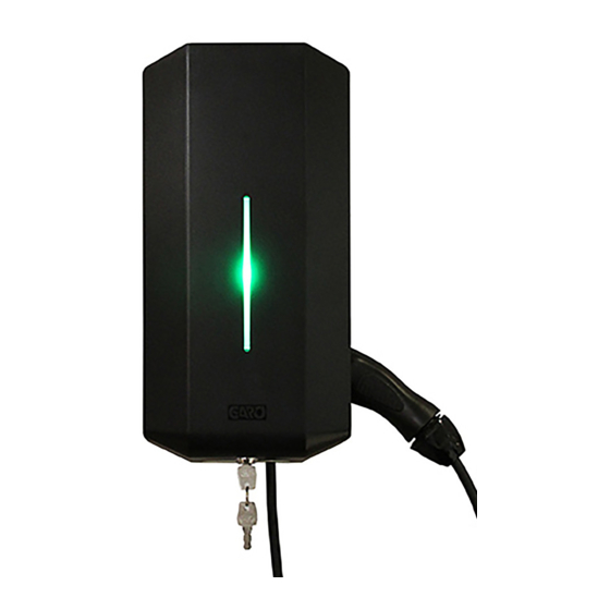
Resumen de contenidos para GARO Wallbox GLB
- Página 1 GARO Wallbox GLB INSTALACIÓN DE UNA GLB WALLBOX...
-
Página 2: Instalación
ÍNDICE TEXTO DE AYUDA DE LA IMAGEN DE LA INSTALACIÓN ADVERTENCIAS PRECAUCIONES NOTAS INSTALACIÓN DE UNA GLB WALLBOX USO/CARGA NORMALES DETECCIÓN Y RESOLUCIÓN DE PROBLEMAS SOFTWARE DEL GLB PUESTA A PUNTO/MANTENIMIENTO DETECCIÓN Y RESOLUCIÓN DE PROBLEMAS/SOPORTE/PREGUNTAS FRECUENTES, ETC. TECHNICAL SPECIFICATIONS FORMULARIO DE LA GARANTÍA CONDICIONES DE LA GARANTÍA TEXTO DE AYUDA DE LA IMAGEN DE LA... - Página 3 Sin embargo, puesto que La instalación y prueba incorrectas de la GLB Wallbox GARO se plantea como meta la mejora continua, nos reservamos podría dañar potencialmente la batería del vehículo y/o el derecho a realizar modificaciones en el producto y en el la propia GLB Wallbox.
- Página 4 (7 x T20) Drill template (see the back of the box) TERMINAL BLOCK MAX 10mm² 3-phase Serial no./SSID password Signal cable entrance 1-phase...
- Página 5 OPTIONS DLM METER INSTALLATION (ACCESSORY) Install the DLM meter in the mains cabinet you want to monitor.Use shielded twisted pair cable between the DLM meter and the wallbox. Suitable cables: CAT5 FTP, CAT5e FTP, CAT6 FTP, ELAKY-S, ELAQBY-S or similar. For full DLM manual and settings: www.garoemobility.com/support SET FUSE SIZE IN MAINS CABINET...
- Página 6 REMOTE ENABLE SETTING ON (default): Use when not connected to external enable relay. OFF: Use when connected to external enable relay. MASTER / SLAVE SETTINGS ON (default): Master OFF: Slave Stand allone installation = ON Cluster installation = See Full manual at www.garoemobility.com/support DATALINK END TERMINATION SETTINGS (N/A for stand alone installation)
- Página 7 MAX VEHICLE CHARGING CURRENT (A) SWITCH 2 ON OFF ON OFF...
- Página 8 WALLBOX TYPE ON: Fixed cable OFF: Outlet Main fuse SW1(DIP 1-3) SW2(DIP 1-3) (7 x T20) MAX 1,6 Nm Serial No / SSID...
- Página 9 DIP SWITCH INFORMATION ON OFF Datalink Endtermination ON, OFF ON = Master Mode, OFF = Slave mode Remote enable input function. ON (default) = Open circuit, OFF = Closed circuit Fuse value in mains cabinet, see below table for settings ON OFF ON OFF ON OFF...
-
Página 10: Instalación De Una Glb Wallbox
INSTALACIÓN DE UNA GLB WALLBOX (para obtener información de la instalación del GLB en grupos, Seleccione el grupo de fusibles adecuado (1x6A - consulte el Manual del usuario en 3x32A) y el área del cable para la instalación eléctrica. www.garoemobility.com/support) En algunos países es necesario instalar interruptores de fallo de la toma de tierra. -
Página 11: Uso/Carga Normales
USO/CARGA NORMALES SOFTWARE DEL GLB Consulte el Manual del usuario en www.garoemobility.com/support Conecte el cable de carga al VE. La carga empezará de PUESTA A PUNTO/MANTENIMIENTO inmediato si el VE está listo para cargarse. Consulte el manual de carga de su VE. Consulte el Manual del usuario en www.garoemobility.com/support Una vez finalizada la carga, siga las instrucciones del coche. -
Página 12: Technical Specifications
TECHNICAL SPECIFICATIONS Product type All GLB models Standards / Directives IEC 61851-1 and IEC 61439-7 EMC Classification: 2014/30/EU Installation method: Wall Installation environment: Indoor / Outdoor Location type: Non-restricted Access Rated Voltage: 230V / 400V 50Hz Installation systems: TT, TN and IT systems Charging type: Mode 3 Charging method:... - Página 13 WARRANTY FORM/GARANTIBLANKETT GTB Model: ELECTRICAL INSTALLATION DATA / ELEKTRISK INSTALLATION INFORMATION Group fuse (A): Gruppsäkring (A): Supply cable dimension: Area matningskabel: Cable length: Längd matningskabel: OPTION MODULES / OPTIONS-MODULER RFID yes/no: RFID ja/nej: Communication Module yes/no: Kommunimationsmodul ja/nej: SETTINGS / INSTÄLLNINGAR Mark existing positions: Markera nuvarande inställningar: Serial No:...
- Página 14 GARANTIVILLKOR/ WARRANTY CONDITIONS EU COUNTRIES (EXCEPT SWEDEN) The product benefits from manufacturer´s warranty. The applicable warranty period must be stated in purchase documents from your supplier. The product must be installed by a certified installer / contractor. Proper installation, storage and operation conditions must be obtained. Warranties apply only to products installed in their original installation location.


