Tabla de contenido
Publicidad
Idiomas disponibles
Idiomas disponibles
Enlaces rápidos
.
Write Model Number From Box Here:
© COPYRIGHT 2022 by Russel Brands, LLC
Portable Basketball System
Owners Manual
Toll-Free Customer Service Number for U.S: 1-800-558-5234,
For Canada: 1-800-284-8339,
For Europe: +353 51 379777,
For Australia: 1-300-367-582
This manual, accompanied by sales receipt,
should be saved and kept on hand as a
convenient reference, as it contains important
1
English
WARNING!
READ AND UNDERSTAND
OPERATOR'S MANUAL
BEFORE USING THIS UNIT.
FAILURE TO FOLLOW
OPERATING
COULD RESULT IN INJURY
OR DAMAGE TO PROPERTY.
information about your model.
02/22
ID# M6A92203
INSTRUCTIONS
Publicidad
Tabla de contenido

Manuales relacionados para SPALDING M6A92203


Resumen de contenidos para SPALDING M6A92203
- Página 1 Toll-Free Customer Service Number for U.S: 1-800-558-5234, For Canada: 1-800-284-8339, For Europe: +353 51 379777, For Australia: 1-300-367-582 02/22 ID# M6A92203 © COPYRIGHT 2022 by Russel Brands, LLC...
-
Página 2: Important
ALL basketball systems, including those used for DISPLAYS, MUST be assembled and installed according to instructions. Failure to follow instructions could result in SERIOUS INJURY. It is NOT acceptable to devise a makeshift support system. Email: warrantyservice@custserv.fotlinc.com Spalding PO Box 90015 Bowling Green, KY 42102... - Página 3 Basketball System Warranty Système de basket-ball garantie Basketball-System Garantie Sistema de baloncesto Garantía de dueños 05/2013...
-
Página 4: Height Adjustment
REQUIRED TOOLS AND MATERIALS: HEIGHT ADJUSTMENT WARNING Read and understand warnings listed • 2 Capable Adults below before using this product. TO ADJUST BACKBOARD: Failure to follow these warnings may result 1. Grasp handle in serious injury and/or property damage. and squeeze trigger. -
Página 5: Safety Instructions
TEST-FIT CLOSE TOLERANCE BOLTS To ensure optimal playability of backboard system, a close tolerance fit between the elevator components and hardware is required. Test-fit large bolts into large holes of elevator tubes, backboard brackets, and triangle plates. Carefully rock them in a circular motion to ream out any excess paint from holes if necessary. NOTE: Not all items pictured are included with every model. -
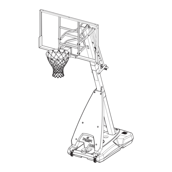
Página 6: Front View
Get to know the basic parts of your basketball system... FRONT VIEW BACKBOARD ELEVATOR ADJUSTMENT SUPPORT STRUT POLE BASE NOTE: BOARD STYLE WILL VARY... -
Página 7: Parts List
205082 Spacer 0.530 I.D. x .38 Long 208251 Spacer, .50 ID x .98 OD x .125 Long 500065 Label, Height Adjustment and Moving 801477 Cover, Spalding 600052 Cap, Pole Top 204007 Nut, Nylock, M4 x 0.7 207550 Axle Nut 208762 Bolt, Hex, M4 x 0.7 x 25mm Long... - Página 8 HARDWARE IDENTIFIER (BOLTS AND SCREWS) #51 (4) #15 (2) #7 (2) 208505 #43 (3) #33 (1) #18 (1) #9 (2) #17 (2) #8 (4) PN 205679 BOLT,HEX HD 1/2-13 X 2", 1.5” THREAD, ZINC PLTD #28 (2) #65 (2) #67 (4) #48 (2) 201596 Screw 1/4 x 1.
- Página 9 HARDWARE IDENTIFIER (NUTS AND WASHERS) #13 (2) #16 (12) #40 (9) 203099Hex Locknut (Nylon Insert) 5/16-18 203100 NUT, HEX FLANGE, 5/16-18 #35 (1) #36 (1) #66 (6) #12 (8) HARDWARE IDENTIFIER (PLASTIC SPACERS, CAPS, CLIPS AND OTHER) #29 (1) #20 (2) #55 (6) #14 (4) #37 (2)
- Página 10 SECTION A: ASSEMBLE THE BASE This is what your system will look like when you’ve finished this section. ITEMS REQUIRED FOR THIS SECTION (2) 1/2”, and (2) 9/16” Wrenches AND/OR (2) Socket Wrenches and Sockets 1/2” 9/16” Wood Board (scrap) WARNING! TWO CAPABLE ADULTS REQUIRED FOR THIS PROCEDURE.
- Página 11 NOTE: IF MINIMUM POLE ENGAGEMENT WHICH ALLOWS THE HARDWARE TO BE ASSEMBLED CANNOT BE ACHIEVED !! STOP !! DO NOT PROCEED TO THE NEXT STEP! - CALL SPALDING CUSTOMER SERVICE FOR ASSISTANCE. WARNING! TWO CAPABLE ADULTS REQUIRED FOR THIS PROCEDURE.
- Página 12 You should have a 4.0” (10.2 cm) overlap when properly assembled. NOTE: IF MINIMUM POLE ENGAGEMENT WHICH ALLOWS THE HARDWARE TO BE ASSEMBLED CANNOT BE ACHIEVED !! STOP !! DO NOT PROCEED TO THE NEXT STEP! - CALL SPALDING CUSTOMER SERVICE FOR ASSISTANCE.
- Página 13 KIT #1 208868 BASE ASSEMBLY - HARDWARE IDENTIFIER KIT #1 #2 (2) #17 (2) #23 (4) #12 (2) Items not included in kit, found in hardware box. #3 (2) #19 (2) PARTS LIST - KIT #1 Item Qty. Part No. Description 10818201 Wheel, Axle 266200 Wheel, 4 Inch...
- Página 14 Install wheel assembly into bottom of base (1). Secure the wheels (3) into the wheel brackets (19) using axles (2) and nuts (23). NOTE Do not install both bolts into the wheel assembly at this time. The front bolt will be installed during strut assembly in Step 3 of this section.
- Página 15 KIT #2 208869 POLE AND STRUTS TO BASE - HARDWARE IDENTIFIER KIT #2 #11 (1) #7 (2) 208247 5/16-18 x 4.75 x 0.875 #9 (2) #15 (6) #13 (1) #16 (6) #12 (4) 208505 203099Hex Locknut (Nylon Insert) 5/16-18 203100 NUT, HEX FLANGE, 5/16-18 Items not included in kit, found in hardware box.
- Página 16 Insert pole assembly into tank assembly as shown. Secure pole assembly (4,5,6) to tank using pole mounting plate (50) and bolts (7) as shown. Secure flat end of tank struts (10) to pole using bolt (11), washer (12), and nut (13), as shown.
- Página 17 Secure cover (39) to base struts (10, 61) using bolts (15) and nuts (16) as shown. Leave bolts (15) and nuts (16) loose until all nuts and bolts have been started. Tighten bolt (11) from Step 5 when complete. IMPORTANT! IMPORTANT! DO NOT OVER TIGHTEN! TIGHTEN ALL HARDWARE FROM THIS STEP...
- Página 18 SECTION B: ATTACH THE BACKBOARD AND GAS STRUT This is what your system will look like when ITEMS REQUIRED FOR THIS SECTION you’ve finished this section. (2) 7mm, (2) 1/2”, (2) 9/16” and (2) 3/4” Wrenches AND/OR (2) Socket Wrenches and Sockets 1/2”...
- Página 19 Bolt, Carriage, 5/16-18 x 4.5” Long 208251 Spacer, .50 ID x .98 OD x .125 Long 206989 Pole Reinforcement Bracket 208829 Plug, Tube, Snap In, 1”, Black 801477 Cover, Spalding 600342 Handle, Gas Lift 208828 Plug, Tube, Snap In, 1.25”, Black 206340 Nut, Nylock, 1/2-13...
- Página 20 Install pole mount bracket (27) and reinforcement bracket (34) with carriage bolts (28) in top pole (4) mounting holes as shown. Tighten flange nuts (16) completely. (FRONT OF POLE) Install gas strut handle arm tubes (53) to middle pole (5) using hex bolt (44) and nylock nut(40) as shown. Insert plugs (38) into tubes (53).
- Página 21 Slide the top cover (56) over the Gas Strut Assembly (54) as shown below. Attach gas strut assembly (54) using bolt (18) and nut (13) to pole mount bracket (27) as shown. Identify and orient the vertical connecting tubes (52) according to the identification stickers and assemble to the handle (59).
- Página 22 Insert bolt (44) through handle arms (53), vertical tubes (52), and the gas strut assembly bracket as shown below. Secure using nut (40) as shown. WARNING! TIGHTEN BOLT (44) IN LOCK NUT (40) UNTIL FLUSH (EVEN) WITH LOCK NUT’S OUTER EDGE.
- Página 23 KIT #4 208796 BOARD ASSEMBLY - HARDWARE IDENTIFIER KIT #4 #49 (1) #51 (4) #65 (2) #66 (6) 201596 Screw 1/4 x 1. #67 (4) #33 (1) #16 (4) 203100 202871 - SCREW HEX WASHR HD TAP SLOTTED 1/4 X 3/4 NUT, HEX FLANGE, 5/16-18 #62 (1) #32 (1)
- Página 24 Install Slam Jam Bracket to Backboard Lay the board on saw horses or a support table. Peel protective film prior to assembly from surface of acrylic backboard. Insert T-bolt (33) into Slam Jam bracket (32) then, attach that assembly to board using bolts (51) and nuts (16).
- Página 25 Install Board Pads to Backboard With the board still on saw horses or a support table. Attach left and right pad sections to board using screws and washers as shown. Using the holes which line up for your board size, attach center pad section to left and right sections and board using screws and washers as shown.
- Página 26 KIT #5 208871 ATTACH BOARD - HARDWARE IDENTIFIER KIT #5 #20 (2) #55 (4) #14 (4) #58 (1) #43 (3) #29 (1) #40 (7) #57 (1) #8 (4) Items not included in kit, found in hardware box. PN 205679 BOLT,HEX HD 1/2-13 X 2", 1.5” THREAD, ZINC PLTD #42 (1) #41 (1) #22 (1)
- Página 27 Identify elevator tubes (41 and 42). Toward Toward Pole Board Lower Elevator Tube Upper Elevator Tube Support pole on sawhorse. Attach upper and lower elevator tubes (41 and 42) to upper pole section (4) using bolts (43), spacers (20), and nuts (40) as shown. Attach lower elevator tubes (41) to gas strut vertical elevator tubes (52) using bolt (43), spacers (68), and nut (40) as shown.
- Página 28 Noting orientation attach lower and upper elevator tubes (41 and 42) to backboard using spacers (14) bolts (8) and nuts (9) as shown. Securely tighten all bolts in this step. WARNING! TWO PEOPLE REQUIRED FOR THIS PROCEDURE. FAILURE TO FOLLOW THIS WARNING COULD RESULT IN SERIOUS INJURY AND/OR PROPERTY DAMAGE.
- Página 29 Fasten the Trigger (60) to the Gas Strut Assembly (54) by using the bolt (58) and nut (57). NOTE: THE TRIGGER WILL BE BETWEEN THE PLATES OF THE BRACKET AND ABOVE THE BOLT (43). SQUEEZING THE TRIGGER WILL ALLOW THE RIM HEIGHT TO BE ADJUSTED.
- Página 30 KIT #6 208877 GOAL ASSEMBLY - HARDWARE IDENTIFIER KIT #6 #48 (2) #36 (1) #35 (1) #31 (1) #30 (1) Items not included in kit, found in hardware box. #47 (1) #24 (1) #25 (1) #26 (1) PARTS LIST - KIT #6 203617 Item Qty.
- Página 31 Install Slam Jam Rim to Backboard A. Fit rim (25) securely into bracket (32) as shown. Allow NOTE: T-bolt (33) to slip through center hole in rim (25). B. Install reinforcement bracket (31) onto T-bolt (33) as shown. ORIENTATION C. Install spring (30) onto T-bolt (33) as shown. OF BRACKET D.
- Página 32 RIM COVER ATTACHMENT Install cover (47) over spring return mechanism using screws (48) as shown. NOTE: Cover plate (47) will fit INSIDE back bracket. NET INSTALLATION Install net (26) onto rim (25). OUTSIDE VIEW...
- Página 33 Instructions for filling with water: Roll completed assembly to desired position. Fill base (1) with water (approx. 34 gallons / 129 Liters) and push in cap (24) securely. CAUTION! WARNING! ADD AT LEAST TWO GALLONS (7.6 LITERS) OF NON-TOXIC ANTIFREEZE IN SUB-FREEZING CLIMATES.
- Página 34 Apply the height adjustment and moving label (21) to the front of the pole as shown. HEIGHT ADJUSTMENT TO ADJUST BACKBOARD: 1. Grasp handle and squeeze trigger. 2. Raise or lower to desired height. 3. Release trigger. MOVING SYSTEM 500065 06/19 10 ft.
- Página 35 Teléfono gratuito de Servicio al Cliente para Estados Unidos: 1-800-558-5234, para Canadá: 1-800-284-8339, para Europa: +353 51 379777, para Australia: 1-300-367-582 02/22 ID NÚM. M6A92203 © COPYRIGHT 2022 de Russell Brands, LLC...
-
Página 36: Importante
TODOS los sistemas de baloncesto, incluidos aquellos utilizados para EXHIBICIONES, DEBEN ser ensamblados e instalados según las instrucciones. El incumplimiento de las instrucciones puede resultar en LESIONES GRAVES. NO es aceptable emplear un sistema de apoyo improvisado. Correo electrónico: warrantyservice@custserv.fotlinc.com Spalding PO Box 90015 Bowling Green, KY 42102... -
Página 37: Système De Basket-Ball Garantie
Sistema de Baloncesto Garantía Para obtener la última información sobre la garantía del Sistema de Baloncesto Visite el sitio web de Spalding Basketball en www.Spalding.com Póngase en contacto con el servicio al cliente de Spalding llamando al teléfono 1-800-558-5234 05/2013... -
Página 38: Ajuste De La Altura
HERRAMIENTAS Y MATERIALES NECESARIOS: AJUSTE DE LA ALTURA • 2 adultos capaces PARA AJUSTAR EL TABLERO: 1. Agarre la manija y presione el gatillo. • Cinta métrica 2. Suba o baje el tablero hasta alcanzar la altura deseada. 3. Suelte el gatillo. •... -
Página 39: Compruebe El Ajuste De Los Pernos De Tolerancia Estrecha
COMPRUEBE EL AJUSTE DE LOS PERNOS DE TOLERANCIA ESTRECHA Para garantizar que el sistema del tablero ofrece una calidad de juego óptima, se requiere una estrecha tolerancia del ajuste entre los componentes del elevador y los herrajes. Compruebe el ajuste de los pernos grandes en los orificios grandes de los tubos del elevador, los soportes del tablero y las placas triangulares. -
Página 40: Vista Frontal
Conozca las piezas básicas del sistema de baloncesto... VISTA FRONTAL TABLERO AJUSTE DEL ELEVADOR PUNTAL DE SOPORTE POSTE BASE NOTA: EL ESTILO DEL TABLERO VARIARÁ... -
Página 41: Lista De Piezas
208251 Espaciador, d. int. 0,50 x d. ext. 0,98 x largo 0,125 de largo 108183 Soporte de las ruedas 801477 Cubierta, Spalding 205082 Espaciador d. int. 0,530 x 0,38 de 204007 Tuerca, Nylock, M4 x 0,7 largo 208762 Perno, hexagonal, M4 x 0,7 x 25 mm... - Página 42 IDENTIFICADOR DE LOS HERRAJES (PERNOS Y TORNILLOS) Núm. 51 (4) Núm. 15 (2) Núm. 7 (2) 208505 Núm. 43 (3) Núm. 33 (1) Núm. 18 (1) Núm. 9 (2) Núm. 17 (2) Núm. 8 (4) PN 205679 BOLT,HEX HD 1/2-13 X 2", 1.5” THREAD, ZINC PLTD Núm.
- Página 43 IDENTIFICADOR DE LOS HERRAJES (TUERCAS Y ARANDELAS) Núm. 13 (2) Núm. 16 (12) Núm. 40 (9) 203099Hex Locknut (Nylon Insert) 5/16-18 203100 NUT, HEX FLANGE, 5/16-18 Núm. 35 (1) Núm. 36 (1) Núm. 66 (6) Núm. 12 (8) IDENTIFICADOR DE LOS HERRAJES (TAPAS, CLIPS, ESPACIADORES DE PLÁSTICO Y OTROS) Núm.
-
Página 44: Sección A: Montaje De La Base
SECCIÓN A: MONTAJE DE LA BASE Así es como se verá su sistema cuando haya terminado esta sección. ARTÍCULOS REQUERIDOS PARA ESTA SECCIÓN (2) 1/2”, y (2) 9/16” Llaves (2) Carracas y llaves de vaso 1/2” 9/16” Tabla de madera (de desecho) ¡ADVERTENCIA! SE REQUIEREN DOS ADULTOS CAPACES PARA ESTE... - Página 45 ¡¡PARE!! NOTA: SI NO PUEDE CONSEGUIR UN ENGANCHE MÍNIMO DEL POSTE QUE PERMITA ENSAMBLAR LOS HERRAJES ¡NO CONTINÚE CON EL SIGUIENTE PASO! - LLAME AL SERVICIO AL CLIENTE DE SPALDING PARA RECIBIR ASISTENCIA. ¡ADVERTENCIA! SE REQUIEREN DOS ADULTOS CAPACES PARA ESTE PROCEDIMIENTO.
- Página 46 NOTA: SI NO SE LOGRA UN ENGANCHE MÍNIMO DEL POSTE QUE PERMITA ENSAMBLAR LOS HERRAJES ¡¡PARE!! ¡NO CONTINÚE CON EL SIGUIENTE PASO! - LLAME AL SERVICIO DE ATENCIÓN AL (PARTE FRONTAL CLIENTE DE SPALDING PARA RECIBIR ASISTENCIA. DEL POSTE) ¡ADVERTENCIA!
- Página 47 KIT Núm. 1 208868 MONTAJE DE LA BASE - KIT IDENTIFICADOR DE LOS HERRAJES NÚM. 1 Núm. 2 (2) Núm. 17 (2) Núm. 23 (4) Núm. 12 (2) Los elementos no incluidos en el kit, se encuentran en la caja de herrajes. Núm.
- Página 48 Inserte el montaje de la rueda en la parte inferior de la base (1). Encaje las ruedas (3) en los soportes de las ruedas (19) empleando los ejes (2) y las tuercas (23). NOTA No instale los dos pernos cuando monte la rueda en este momento.
- Página 49 KIT Núm. 2 208869 POSTE Y PUNTAL A LA BASE - KIT IDENTIFICADOR DE LOS HERRAJES NÚM. 2 Núm. 11 (1) Núm. 7 (2) 208247 5/16-18 x 4.75 x 0.875 Núm. 9 (2) Núm. 15 (6) Núm. 13 (1) Núm. 16 (6) Núm.
- Página 50 Inserte el montaje del poste en el montaje del tanque como se muestra. Fije el conjunto de postes (4,5,6) al tanque utilizando la placa del montaje del poste (50) y los pernos (7) como se muestra. Fije el extremo plano de los puntales del tanque (10) al poste utilizando el perno (11), la arandela (12), y la tuerca (13), como se muestra.
- Página 51 Fije la cubierta (39) sobre los puntales de la base (10, 61) utilizando los pernos (15) y tuercas (16) como se muestra. Deje sueltos los pernos (15) y tuercas (16) hasta que haya colocado todas las tuercas y pernos. Apriete el perno (11) del Paso 5 cuando termine.
-
Página 52: Sección B: Fije El Tablero Y El Puntal De Gas
SECCIÓN B: FIJE EL TABLERO Y EL PUNTAL DE GAS Así es como se verá su sistema cuando haya ARTÍCULOS REQUERIDOS PARA ESTA SECCIÓN terminado esta sección. (2) 7 mm, (2) 1/2”, (2) 9/16” y (2) 3/4” Llaves (2) Carracas y llaves de vaso 7 mm 1/2”... - Página 53 Espaciador, d. int. 0,50 x d. ext. 206989 Soporte de refuerzo del poste 0,98 x 0,125 de largo 208829 Tapón, tubo, a presión, 1”, negro 801477 Cubierta, Spalding 208828 Tapón, tubo, a presión, 1,25”, 600342 Manija, inyección de gas negro 206340...
- Página 54 Instale el soporte del montaje del poste (27) y el soporte de refuerzo (34) con los pernos de carruaje (28) en los orificios de montaje del poste superior (4) tal y como se indica. Apriete las tuercas bridadas (16) por completo.
- Página 55 Deslice la cubierta superior (56) sobre el montaje del puntal de gas (54) como se muestra a continuación. Fije el conjunto del puntal de gas (54) utilizando el perno (18) y la tuerca (13) al soporte de montaje del poste (27) como se muestra.
- Página 56 Inserte el perno (44) a través de los brazos de la manija (53), los tubos verticales (52) y el soporte del montaje del puntal de gas como se muestra a continuación. Fíjelo con una tuerca (40) como se muestra. ¡ADVERTENCIA! APRIETE EL PERNO (44) EN LA CONTRATUERCA (40) HASTA QUEDAR PAREJO CON EL BORDE EXTERIOR DE LA CONTRATUERCA.
- Página 57 KIT Núm. 4 208796 MONTAJE DEL TABLERO - KIT IDENTIFICADOR DE HERRAJES NÚM. 4 Núm. 49 (1) Núm. 51 (4) Núm. 65 (2) Núm. 66 (6) 201596 Screw 1/4 x 1. Núm. 67 (4) Núm. 33 (1) Núm. 16 (4) 203100 202871 - SCREW HEX WASHR HD TAP SLOTTED 1/4 X 3/4 NUT, HEX FLANGE, 5/16-18...
- Página 58 Coloque el soporte Slam Jam en el tablero Coloque el tablero sobre el caballete o la mesa de soporte. Despegue la película protectora de la superficie del tablero acrílico antes del montaje. Inserte el perno en T (33) en el soporte Slam Jam (32) y, a continuación, fije ese conjunto al tablero utilizando los pernos (51) y las tuercas (16).
- Página 59 Coloque las almohadillas del tablero en el tablero Mantenga el tablero colocado sobre el caballete o la mesa de apoyo. Coloque las secciones izquierda y derecha de la almohadilla en el tablero usando tornillos y arandelas como se muestra. Utilizando los orificios, que se alinean según el tamaño de su tablero, fije la sección central de la almohadilla en las secciones izquierda y derecha y en el tablero utilizando tornillos y arandelas, tal y como se indica.
- Página 60 KIT Núm. 5 208871 INCORPORE EL TABLERO - KIT IDENTIFICADOR DE LOS HERRAJES NUM. 5 Núm. 20 (2) Núm. 55 (4) Núm. 14 (4) Núm. 58 (1) Núm. 43 (3) Núm. 29 (1) Núm. 40 (7) Núm. 57 (1) Núm. 8 (4) Los elementos no incluidos en el kit, se encuentran en la caja de herrajes.
- Página 61 Identifique los tubos del elevador (41 y 42). Hacia el Hacia el poste tablero Tubo inferior del elevador Tubo superior del elevador Apoye el poste en el caballete. Fije los tubos superiores e inferiores del elevador (41 y 42) a la sección del poste superior (4) utilizando los pernos (43), espaciadores (20) y tuercas (40) como se muestra.
- Página 62 Teniendo en cuenta la orientación, fije los tubos inferiores y superiores del elevador (41 y 42) al tablero con espaciadores (14), pernos (8) y tuercas (9) como se muestra. Apriete de forma segura todos los pernos en este paso. ¡ADVERTENCIA! SE REQUIEREN DOS PERSONAS PARA ESTE PROCEDIMIENTO.
- Página 63 Fije el gatillo (60) en el montaje del puntal de gas (54) utilizando el perno (58) y la tuerca (57). NOTA: EL GATILLO ESTARÁ SITUADO ENTRE LAS PLACAS DEL SOPORTE Y POR ENCIMA DEL PERNO (43). AL APRETAR EL GATILLO SE PODRÁ AJUSTAR LA ALTURA DEL ARO.
- Página 64 KIT Núm. 6 208877 MONTAJE DE LA CANASTA - KIT IDENTIFICADOR DE LOS HERRAJES NÚM. 6 Núm. 48 (2) Núm. 36 (1) Núm. 35 (1) Núm. 31 (1) Núm. 30 (1) Los elementos no incluidos en el kit, se encuentran en la caja de herrajes. Núm.
- Página 65 Instale el aro "Slam Jam" en el tablero A. Coloque el aro (25) firmemente en el soporte (32) como se muestra. Permita que el perno en T (33) se deslice a través NOTA: del orificio central en el aro (25). B.
-
Página 66: Fijación De La Cubierta Del Aro
FIJACIÓN DE LA CUBIERTA DEL ARO Instale la cubierta (47) sobre el mecanismo de retorno por resorte con los tornillos (48) como se muestra. NOTA: La placa de la cubierta (47) encajará DENTRO del soporte trasero. INSTALACIÓN DE LA RED Coloque la red (26) en el aro (25). - Página 67 Instrucciones para el llenado con agua: Mueva el conjunto completado a la posición deseada. Llene la base (1) con agua (aproximadamente 34 galones / 129 litros) y empuje la tapa (24) de forma segura. ¡PRECAUCIÓN! ¡ADVERTENCIA! AGREGUE 2 GALONES (7,6 LITROS) DE ANTICONGELANTE NO TÓXICO EN CLIMAS CON TEMPERATURAS BAJO CERO.
- Página 68 Aplique la etiqueta de ajuste de altura y movilización (21) en la parte delantera del poste como se muestra. AJUSTE DE LA ALTURA PARA AJUSTAR EL TABLERO: 1. Agarre la manija y presione el gatillo. 2. Suba o baje el tablero hasta alcanzar la altura deseada.