Registrarse
Cargar
Manuales
Marcas
Nordson Manuales
Máquinas de Fusión
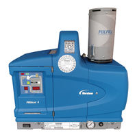
ProBlue P10
Nordson ProBlue P10 Manuales
Manuales y guías de usuario para Nordson ProBlue P10. Tenemos
1
Nordson ProBlue P10 manual disponible para descarga gratuita en PDF: Manual De Instrucciones
Nordson ProBlue P10 Manual De Instrucciones (320 páginas)
Marca:
Nordson
| Categoría:
Máquinas de Fusión
| Tamaño: 4.96 MB
Tabla de contenido
English
3
Tabla de Contenido
3
Nordson International
11
Europe
11
Distributors in Eastern & Southern Europe
11
Outside Europe / Hors D'europe / Fuera de Europa
12
Africa / Middle East
12
Asia / Australia / Latin America
12
Japan
12
North America
12
Troubleshooting
121
400/480 Volt Melters
121
Safety
121
Melter Faults
122
Using the Troubleshooting Flowchart
124
Troubleshooting Quick-Checks
124
Returning the Melter Setup to Factory Settings
125
Identifying Electrical Components
125
Diagnostic Procedures
131
DP.1 Isolate a Failed Control Component
131
DP.2 Check the Tank or Manifold RTD
132
Reheating the Melter During an F1 Fault
133
Remove the Tank RTD
133
Remove the Manifold RTD
134
DP.3 Check the Operation of the Power Relay or Thermostats
135
DP.4 Check the Operation of the Tank or Manifold TRIAC
136
DP.5 Check the Resistance of the Tank and Manifold Heaters
137
Problue Troubleshooting Flowcharts
141
Parts
167
Using the Illustrated Parts List
167
Fasteners
167
Tank, Pump, and Manifold Parts List
168
Manifold Assembly Parts List
170
Pump Assembly Parts Lists
173
15:1 Pump Assembly Parts
173
15:1 Low-Viscosity Pump Assembly Parts
176
6:1 Pump Assembly Parts
180
Pump Shifter Assembly Parts
184
Pump Piston Assembly Parts
186
Pneumatic Components Parts List
188
Electrical Enclosure Parts List
190
Exterior Panels Parts List
192
Chassis Components Parts List
194
Ribbon Cable Parts List
196
Service Kits
197
15:1 Pump Replacement
197
15:1 Low-Viscosity Pump Replacement
197
Pump General Service
198
Filter
198
Pneumatic Panel
198
Pressure Discharge Valve
199
Manifold Service Kit
199
Thermostat
199
Main Circuit Board
200
Central Processor Unit (CPU)
200
Operator's Panel
200
Hose/Gun Module
200
Main Circuit Board Fuses
200
Hose/Gun Module Fuses
201
Basic Spare Parts
201
Expanded Spare Parts
201
Level Switch
201
Manifold Guard (P4)
202
Manifold Guard (P10)
202
Vent Guard (P10)
202
Replacement Tank
202
Tank Lid Hinge Pin
202
Heater Block 230V
203
Manifold 4- or 6-Hose/230V or 480V
203
Option Kits
204
6-Hose Extension
204
Input/Output Expansion Card
204
Fill Master
204
Ethernet Card
204
Devicenet Card
205
Profibus Card
205
P10 8 H/G Expansion Base
205
Schedule of Fasteners
206
Technical Data
207
General Specifications
207
Electrical Specifications
208
Pump Specifications
208
Melter Power Requirements
208
Dimensions
209
P4 Melter
209
P7 Melter
210
P10 Melter
211
Sub-Base
212
Wiring Diagrams-200/240 VAC Melter
213
Melter Communications
251
Software Availability
251
System Requirements
251
Installing the Software
252
Removing the Software from Your PC
254
Connecting the PC and the Melter
255
Using Nordson Configuration Manager
256
Saving and Restoring Melter Settings
256
Upgrading or Restoring Melter Firmware
258
Troubleshooting
261
Using Nordson Configuration Manager
261
SP Pump Diagnostics and Repair
263
Introduction
263
Pump Function
263
Pump Isolation Valve
264
Pressure Discharge Valve
264
Pump Diagnostics
266
Pump Disassembly and Reassembly
268
Melter Preparation
268
Required Tools and Materials
268
Tools
268
Service Parts
269
Supplies
269
Remove the Pump from the Melter
270
Special Reassembly Instructions
270
Remove the Actuator and Air Manifold and the Cylinder Assembly
272
Special Reassembly Instructions
272
Remove the Magnetic Actuator Assembly
274
Remove the Valve Spool and Sleeve
277
Special Reassembly Instructions
278
Remove the Shifter Fork
280
Special Reassembly Instructions
280
Remove the Piston Cups
282
Special Reassembly Instructions
282
Remove the Pump Frame and the Insulator
284
Special Reassembly Instructions
284
Remove the Lower Ball Seat Assembly and the Piston
288
Special Reassembly Instructions
288
Disassemble the Lower Ball Seat and the Pressure Ball Assemblies
290
Special Reassembly Instructions
290
Remove the O-Ring and the Pump Seal
292
Special Reassembly Instructions
292
Pump Assembly Parts List
294
Pump Service Kit
296
Other Pump Maintenance Kits
296
Schedule of Fasteners
296
400/480 Volt Problue Adhesive Melters
297
Intended Use
298
Unintended Use
298
Transformer Sizing
299
Transformer Function
301
Installation
302
Clearances
302
Installation Kit Components
303
Prepare the Transformer for Installation
304
Mount the Transformer to the Parent Machine
306
Connect the Electrical Service to the Transformer
308
Mount the Melter to the Transformer
310
Connect the Transformer to the Melter
312
Troubleshooting
315
Parts
316
Transformer Assembly
318
400/480-Volt Melter-Specific Components
319
Service Kits
319
Wiring Diagram
319
Spanish
13
Señales de Alerta de Seguridad
13
Responsabilidades del Propietario del Equipo
14
Información de Seguridad
14
Instrucciones, Requisitos y Normas
14
Cualificaciones del Usuario
15
Prácticas de Seguridad de la Industria Aplicables
15
Uso Previsto del Equipo
15
Instrucciones y Mensajes de Seguridad
16
Prácticas de Instalación
16
Procedimientos Operativos
16
Procedimientos de Mantenimiento y Reparación
17
Información de Seguridad del Equipo
17
Parada del Equipo
18
Eliminar la Presión Hidráulica del Sistema
18
Desconectar la Alimentación del Sistema
18
Deshabilitación de Los Aplicadores
18
Avisos de Seguridad Generales y Precauciones
19
Otras Precauciones de Seguridad
22
Primeros Auxilios
22
Etiquetas y Rótulos de Seguridad
23
Introducción
25
Otras Fuentes de Información
26
Guía de Instalación
26
Guía del Usuario
26
Asistencia Online
26
CD de Recursos del Producto
26
Descripción del Producto
27
Uso Previsto
28
Restricciones de Uso
28
Modos de Funcionamiento
28
Identificación del Fusor
29
Componentes Clave
30
Equipamiento Opcional
32
Instalación
33
Rápida Puesta en Marcha
33
Instalación de Fusores de 400/480 Voltios
33
Resumen
34
Información Adicional
34
Tareas de Instalación
35
Experiencia del Personal de Instalación
35
Requerimientos de Instalación
36
Distancias
36
Ventilación
37
Tensión Eléctrica
37
Aire Comprimido
38
Otras Consideraciones
38
Desembalaje del Fusor
40
Contenido del Kit de Instalación
40
Materiales Suministrados por el Cliente
40
Montaje del Fusor
42
Configuración del Servicio Eléctrico
45
Conexión de un Suministro de Aire Comprimido
50
Conexión de Mangueras y Pistolas
52
Configuración del Fusor
56
Configuración Rápida
56
Parámetros de Funcionamiento
58
Selección de Parámetros de Funcionamiento
58
Lectura O Edición de Parámetros de Funcionamiento
58
Temperatura de Punto de Referencia del Tanque, Mangueras y Pistolas
64
Guardar y Restablecer Ajustes del Fusor
66
Revisión de Cambios en Parámetro y Temperatura de Punto de Referencia
68
Instalación de Entradas de Fusor
72
Instalación de Salidas del Fusor
76
Instalación de Equipamiento Opcional
79
Conexión de un Accionador de Pistola, un Controlador de Encolado O un Temporizador
79
Purga del Fusor
79
Ajuste de las Comunicaciones del Fusor
79
Manejo
81
Información Adicional
81
Más Acerca de Los Componentes Calefactados
82
Llenado del Tanque
83
Puesta en Marcha del Fusor
84
Control del Fusor
86
Confirmar que el Fusor Está Funcionando Correctamente
87
Control de Temperaturas de Componente
88
Control de Fallos del Fusor
90
Cómo Se Manejan Los Fallos F1, F2 y F3
94
Cómo Se Manejan Los Fallos F4
95
Control del Nivel de Adhesivo Termofusible en el Tanque
97
Control y Ajuste de la Presión de Aire de Trabajo
97
Control del Intervalo de Servicio
98
Ajuste de Temperaturas de Componente
99
Introducir la Contraseña del Fusor
104
Utilización de las Teclas de Función del Fusor
105
Tecla Calefactor
105
Tecla Bomba
106
Tecla Ajuste
106
Tecla de Reloj Programador Semanal
107
Tecla Reposo
108
Desconexión del Fusor
109
Mantenimiento
111
Eliminar la Presión del Sistema
112
Bloqueo de Comunicaciones Externas
112
Limpieza del Fusor
114
Sustitución del Filtro
116
Limpieza del Tanque
118
Retirar el Fusor de la Base Inferior
120
Cálculo de Requerimientos de Tensión del Fusor
224
Parámetros de Funcionamiento
227
Estándar
228
Control de Temperatura
232
Ajuste de Entrada
235
Ajuste de Salida
238
Reloj Programador Semanal
240
Ejemplo 1
241
Ejemplo 2
241
Publicidad
Publicidad
Productos relacionados
Nordson ProBlue P4
Nordson ProBlue P7
Nordson ProBlue P15
Nordson PICO Pulse
Nordson PS3
Nordson PURBlue EC
Nordson ProBlue 4
Nordson ProBlue 10
Nordson ProBlue 15
Nordson ProBlue 30
Nordson Categorias
Equipo Industrial
Pulverizador Pintura
Controladores
Máquinas de Fusión
Bombas
Más Nordson manuales
Login
Entrar
O
Iniciar sesión con Facebook
Iniciar sesión con Google
Cargar el manual
Cargar desde el disco
Cargar desde la URL