Astralpool PC 2000 Manual De Instrucciones
Ocultar thumbs
Ver también para PC 2000:
- Manual de instrucciones (13 páginas) ,
- Manual de instrucciones (11 páginas)
Tabla de contenido
Publicidad
Idiomas disponibles
Idiomas disponibles
Enlaces rápidos
Publicidad
Tabla de contenido

Manuales relacionados para Astralpool PC 2000


Resumen de contenidos para Astralpool PC 2000
- Página 1 Manual de Instrucciones PC 2000 pH – redox – temperatura Manual: Versión: 1.0...
- Página 2 Índice: 1___DATOS TÉCNICOS pág. 3 2___CONEXIONES EN LA BORNERA pág. 4 3___PANEL DE MANDOS pág. 5 3.1___DESCRIPCIÓN GENERAL DEL TECLADO pág. 6 3.2___DESCRIPCIÓN GENERAL DE LOS INDICADORES LUMINOSOS 4___ENCENDIDO Y CONFIGURACIONES PRELIMINARES pág. 7 5___CALIBRACIÓN INSTRUMENTO pág. 8 pág. 9 5.1___CALIBRACIÓN SONDA pH pág.
-
Página 3: Datos Técnicos
1___DATOS TÉCNICOS MEDIDAS: 240 mm – 245 mm – 140 mm GRADO DE PROTECCIÓN: IP65 (salvo BNC) SECCIÓN DE LOS BORNES: , o diámetro 2,4 mm ALIMENTACIÓN: standard 230V ± 10% 50-60 Hz. Bajo pedido 115V CONSUMO: 7W + 9W electroválvula CAPACIDAD MÁXIMA EN RELÉS: 3A (con carga resistiva) 250 Vac TEMPERATURA DE TRABAJO... -
Página 4: Descripción
CONEXIONES EN LA BORNERA 2___ N° Borne Descripción TIERRA FASE NEUTRO 4 – 5 RELÉ BOMBA PH 6 – 7 RELÉ BOMBA CLORO 8 – 9 RELE ALARMA 10 – 11 RELÉ E.V. 12 – 14 INPUT SEÑAL KEY 13 – 14 INPUT SEÑAL FLUS NO UTILIZADO NO UTILIZADO... -
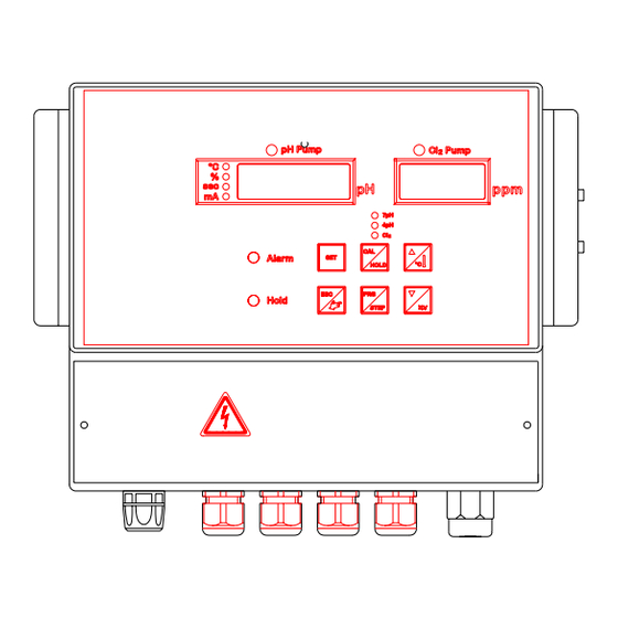
Página 5: Panel De Mandos
3___PANEL DE MANDOS DESCRIPCIÓN GENERAL DEL TECLADO Visualiza en secuencia los set point configurados, si la función está habilitada permite cambiar su valor. Utilizado al mismo tiempo con la tecla ACK permite forzar el estado de los relés de set. Presionando tecla aparece... -
Página 6: Descripción General De Los Indicadores Luminosos
3.2 DESCRIPCIÓN GENERAL DE LOS INDICADORES LUMINOSOS Display de la medida pH Display de la medida Redox Diodo LED bicolor. Indica el estado de la bomba pH APAGADO La bomba del pH está apagada VERDE El set point está activo pero la bomba está temporalmente apagada ROJO El set point está... -
Página 7: Encendido Y Configuraciones Preliminares
UNIDAD DE MEDIDA ° C El valor numérico visualizado es una temperatura expresada en °C Si este indicador está encendido al mismo tiempo que el led %, significa que el valor numérico visualizado es un coeficiente de corrección según temperatura expresado en %/°C. - Página 8 5___CALIBRACIÓN Para entrar en el menú Calibración mantener pulsada la tecla durante 5 segundos, el instrumento presenta el mensaje Hold Cal; después de dicho tiempo aparece el mensaje PH CAL con el LED Hold encendido. Utilizando la tecla seguirán cíclicamente las palabras PH, ORP, CRT.
-
Página 9: __Calibración Sonda Ph
La operación de calibración del electrodo es controlada de manera semiautomática por el instrumento PC 2000, que reconoce de manera autónoma el valor de norma de la solución patrón en la cual está sumergido el electrodo y que visualiza un parámetro de calidad para indicar el grado de agotamiento de la sonda. - Página 10 Presionar la tecla el valor de la solución tampón es reconocida. Presionar la tecla en el display aparece el mensaje OFFS PH. Esperar 30 segundos para la calibración de la sonda. El instrumento calcula el valor de OFFSET y visualiza la calidad del electrodo en porcentaje.
-
Página 11: __Calibración Sonda Redox
Presionar la tecla . En el display aparece el mensaje GAIN PH. Esperar 30 segundos. El instrumento calcula el valor de GAIN y visualiza la calidad del electrodo en porcentaje. El instrumento guarda los parámetros calculados y visualiza durante un segundo en el display SAVE PAR. -
Página 12: __Verificación Sondas
Presionar la tecla el valor de la solución tampón es reconocida. Presionar la tecla , en el display aparece el mensaje OFFS MV. Esperar 30 segundos para la calibración de la sonda. El instrumento calcula el valor de OFFSET y visualiza la calidad del electrodo en porcentaje. - Página 13 Presionar la tecla En el display aparece G100 Ctr con el led 4 pH y % encendido, el instrumento indica la calidad GAIN del electrodo pH. Presionar la tecla En el display aparece o100 Ctr con el led Cl encendido, el instrumento indica la calidad OFFSET del electrodo Redox.
-
Página 14: Menú Programación
6___MENÚ PROGRAMACIÓN Para acceder al menú programación mantener presionada la tecla durante 5 segundos. En el display aparece PROG Entra en la función de programación, es visualizada la palabra 0 PAS, con las teclas configurar el número de contraseña. Presionando la tecla con la palabra 255 PAS se accede al menú... -
Página 15: __Lista De Las Variables Menú Completo
VARIABLES LÍMITES VALORES POR DEFECTO COMENTARIO CONSENTIDOS CONFIGURACIONES PH 0…14,00 7,20 SET POINT pH 0…SET 6,80 Alarma mínimo pH SET…14,00 7,60 Alarma máximo pH CONFIGURACIONES Redox 0…999 mV SET POINT redox 0…SET Alarma mínimo redox SET…999 Alarma máximo redox HABILITACIONES ON/OFF Habilita la Tecla Set ON/OFF... -
Página 16: Regulaciones
7___REGULACIONES 7.1___ON / OFF Es la regulación más simple y elemental que se puede efectuar. El dosificador es encendido cuando se sobrepasa la medida del SET POINT y es apagado cuando la medida vuelve por debajo de un cierto valor configurado que es definido como histéresis. La HISTÉRESIS permite evitar continuas activaciones-desactivaciones del aparato dosificador, una histéresis reducida mejora la regulación pero conlleva un mayor desgaste del dosificador. - Página 17 Ejemplo: Si configuramos un set point pH = 7,20 pH y una banda de guardia BND = 0,20 pH podemos ajustar un tiempo de Ton y Tof entre 7,20 pH y 7,40 pH. Si configuramos un set point Redox = 700 mV de cloro y una banda de guardia BND = 50 mV podemos ajustar un tiempo de Ton y Tof entre 650 ppm y 700 ppm.
-
Página 18: __ Regulación Proporcional En Corriente
7,3___SALVAGUARDIA PARÁMETROS Para guardar los parámetros configurados en el menú de programación presionar la tecla durante 5 segundos y esperar el mensaje SAVE PAR. 7.4___ REGULACIÓN PROPORCIONAL EN CORRIENTE La regulación proporcional en corriente es posible configurarla con las variables: 0 ph Valor inicial para reg. -
Página 19: __Protección De La Programación
La alarma de flujo se activa si la señal de falta de flujo queda activa continuamente durante 40 segundos, en tal caso, además de ver el led Alarma intermitente en el display de medida del pH, el mensaje FLUS se alterna a la visualización de la medida. NOTA: En el estado de alarma flujo las salidas en corriente son forzadas a 0 mA. -
Página 20: Memo De Programación
8___MEMO DE PROGRAMACIÓN VARIABLES VALORES POR COMENTARIO CONFIGURACIONES DEFECTO CONFIGURACIONES PH 7,20 SET POINT pH ACID Tipo de regulación 6,80 Alarma mínimo pH 7,60 Alarma máximo pH Estado relé pH 0,05 Histéresis Tiempo de retraso dos. Tiempo de On (Reg. Puls.) Tiempo de Of (Reg. - Página 21 Instruction Manual PC 2000 (Cod.136314) pH – redox – temperature Manual:0000136314 Products: PC2000 Version: 2.0...
- Página 22 Table of contents: 1___TECHNICAL SPECIFICATIONS Page 3 2___CONNECTION TO THE TERMINAL STRIP Page 4 3___CONTROL PANEL Page 5 Page 5 3.1___GENERAL DESCRIPTION OF THE KEYPAD Page 6 3.2___GENERAL DESCRIPTION OF THE SIGNALLING LAMPS 4___SWITCHING ON AND PRELIMINARY SETTINGS Page 7 5___CALIBRATING THE INSTRUMENT Page 8 Page 9...
-
Página 23: Technical Specifications
1___TECHNICAL SPECIFICATIONS SIZE: H – L – D CLASS OF PROTECTION: IP65 (excluding BNC) CROSS-SECTION OF TERMINALS: 4 mm , or diameter 2.4 mm POWER SUPPLY REQUIREMENTS: standard 230V 10% 50-60 Hz, 115V on request CURRENT ABSORPTION: 7W + 9W for solenoid valve MAXIMUM CAPACITY ON RELAYS: 3A (on a resistive load), 250 VAC WORKING TEMPERATURE... - Página 24 2___CONNECTIONS TO THE TERMINAL STRIP: Terminal Nr Description NEUTRAL PHASE 3 – 4 RELAY S.V. (SOLENOID VALVE) 5 – 6 RELAY PH PUMP 7 – 8 RELAY CHLORINE PUMP 9 – 10 RELAY ALARM 11 – 12 NOT USED NOT USED NOT USED PT100 INPUT PT100 INPUT...
-
Página 25: Control Panel
3___CONTROL PANEL GENERAL DESCRIPTION OF THE KEYPAD This key displays the set points entered, in sequence. If this function is enabled, the key can be used to change the set-point value. Used together with the ACK key enables the status of the set-point relays to be forced. When this key is pressed, the wording ProG will be displayed. - Página 26 GENERAL DESCRIPTION OF THE SIGNALLING LAMPS pH measurement display Redox measurement display Two-coloured LED. It indicates the status of the pH pump The pH pump is OFF. GREEN The set point is active but the pump is temporarily OFF. The set point is active and the pump is ON. FLASHING RED During programming it indicates that the parameter being displayed refers to control of the pH set point.
- Página 27 UNITS OF MEASUREMENT °C The numerical value being displayed is a temperature expressed in °C. If this indicator is illuminated at the same time as the % sign, this means that the numerical value being displayed a correction factor that depends on the temperature. It is expressed in %/°C.
- Página 28 5___CALIBRATION To enter the calibration menu, hold the key down for 5 seconds. The instrument will display the message Hold Cal. After this lapse of time, the message CL CAL will appear and the Hold LED will light up. If the key is pressed repeatedly, the items PH, ORP, CRT will follow cyclically.
- Página 29 The pH electrode has to be re-calibrated periodically, until it is too exhausted, at which point it will have to be replaced. The electrode calibration operation is controlled semi-automatically by the PC 2000 instrument, which is able to recognise on its own the standard value of the sample solution into which the electrode is dipped, and will display a quality parameter to indicate its degree of exhaustion.
- Página 30 Press the key to confirm the value of the buffer solution as recognised. Press the key. The indication OFFS PH will appear on the display. Wait 30 seconds for the probe to be calibrated. The instrument will calculate the OFFSET value show the quality of the electrode as a percentage.
- Página 31 Press the key. The indication GAIN PH will appear on the display. Wait for 30 seconds while the instrument calculates the GAIN. It will then show the quality of the electrode as a percentage. The instrument will save the parameters that have been calculated and the wording SAVE PAR will appear on the display for 1 second.
- Página 32 Press the key to confirm the value of the buffer solution as recognised. Press the key. The indication OFFS MV will appear on the display. Wait 30 seconds for the probe to be calibrated. The instrument will calculate the OFFSET value and show the quality of the electrode as a percentage value.
- Página 33 Press the key. The indication G100 Ctr will appear on the display with the 4 pH and % LEDs illuminated. The instrument indicates the GAIN quality of the pH electrode. Press the key. The indication o100 Ctr will appear on the display with the Cl and % LEDs illuminated.
- Página 34 6___PROGRAMMING MENU To access the programming menu hold the key down for 5 seconds. The message PROG will appear on the display. On entering the programming function, the first item - 0 PAS – will appear on the display. Use the keys to set the password number.
- Página 35 6.1___LIST OF VARIABLES ON THE SHORT MENU (255) VARIABLES PERMITTED LIMITS DEFAULT VALUES COMMENTS PH SETTINGS 0…14,00 7,20 pH SET POINT 0…SET 6,80 Minimum PH alarm SET…14,00 7,60 Maximum pH alarm Redox settings 0…999 mV Redox SET POINT 0…SET Minimum redox alarm SET…999 Maximum redox alarm ENABLING...
- Página 36 7___CONTROL MODES 7.1___ON / OFF This is the simplest and most elementary control mode that can be implemented. The metering device switches on as soon as the measured value exceeds the SET POINT and switches off when the measured value drops to below a given pre-set value that is defined as HYSTERESIS. HYSTERESIS makes it possible to prevent the metering device from switching constantly on and off.
- Página 37 7.2___PROPORTIONAL IN TIME Example: If we enter a pH set point = pH 7.20 and a safety range BND = pH 0.20, we can control the pH, keeping it between 7.20 and 7.40 with the Ton and Tof times. If we enter a Redox set point = 700 mV of chlorine and a safety range BND = 50 mV, we can control the content, keeping it between 650 ppm and 700 ppm with the Ton and Tof times.
-
Página 38: __Saving The Parameters
7.3___SAVING THE PARAMETERS To save the parameters set in the programming menu, press the key, holding it down for 5 seconds and waiting for the SAVE PAR message. 7.4___CURRENT-PROPORTIONAL CONTROL It is possible to set current-proportional control by means of the following variables: pH 0 Initial value for mA control pH 14,00... - Página 39 The flow alarm is activated if enabling remains active without a break for 40 seconds. In this case, in addition to seeing the alarm LED flashing on the pH measurement display, the indication FLUS will be displayed alternating with the measured value. N.B.
- Página 40 8___PROGRAMMING MEMO VARIABLES DEFAULT VALUES COMMENTS SETTINGS PH SETTINGS 7,20 SET POINT pH ACID Type of control 6,80 Minimum pH alarm 7,60 Maximum pH alarm Status of the pH relay 0,05 Hysteresis Delay time, pH metering ON time (Pulsed control) OFF time (Pulsed control) Safety range 4-20...