Tabla de contenido
Publicidad
Idiomas disponibles
Idiomas disponibles
Enlaces rápidos
Publicidad
Capítulos
Tabla de contenido
Solución de problemas

Manuales relacionados para Truper SINCO-10X2


Resumen de contenidos para Truper SINCO-10X2
- Página 1 Instructivo para Sierra de inglete 1 900 W compuesta telescópica Este instructivo es para: Modelo Código SINCO-10X2 16869 SINCO-10X2 Lea este Instructivo por completo ATENCIÓN antes de usar la herramienta.
-
Página 2: Tabla De Contenido
Desempaque y montaje Guarde este instructivo para futuras Montaje referencias. Ajustes Los gráficos de este instructivo son para referencia, pueden variar del Operación aspecto real de la herramienta. Solución de problemas Mantenimiento Notas Centros de Servicio Autorizados Póliza de Garantía SINCO-10X2 ESPAÑOL... -
Página 3: Especificaciones Técnicas
Especificaciones técnicas SINCO-10X2 Código 16869 Descripción Sierra de inglete compuesta telescópica Disco 250 mm (10”) de 40 dientes Diámetro del eje 16 mm (5/8”) (flecha) Tensión Frecuencia 127 V 60 Hz Corriente 15 A Potencia 1 900 W - 2... -
Página 4: Advertencias Generales De Seguridad Para Herramientas Eléctricas
Advertencias generales de seguridad para herramientas eléctricas ¡ADVERTENCIA! Lea detenidamente todas las advertencias de seguridad y todas las instrucciones que se enlistan a continuación. La omisión de alguna de ellas puede dar como resultado un choque eléctrico, incendio y/o daño serio. Conserve las advertencias y las instrucciones para futuras referencias. Área de trabajo No sobrepase su campo de acción. -
Página 5: Advertencias De Seguridad
Advertencias de Seguridad para uso de sierras estacionarias • Antes de instalar un disco nuevo cerciórese de que no Generales tenga golpes o daños. Si así fuera reemplácelo de • No use la sierra para cortar metales ferrosos, inmediato. mampostería o concreto. •... -
Página 6: Partes
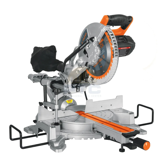
Partes 1. Cabezal de corte. 2. Seguro de interruptor. 3. Seguro de bloqueo del cabezal de corte. 4. Mango. 5. Interruptor. 6. Mango de transporte. 7. Guarda superior del disco. 8. Guarda retráctil. 9. Brazo retractor de la guarda. 10. Disco de corte de 250 mm (10”) de carburo de tungsteno de 40 dientes. -
Página 7: Desempaque Y Montaje
Partes Vista posterior del mango Desempaque y montaje Gracias a estrictos controles de calidad es muy poco Montaje sobre banco de trabajo probable que su herramienta presente algún defecto o • La base de la herramienta cuenta con orificios en cada uno que le falte alguna pieza. -
Página 8: Montaje
Montaje Brazos de extensión lateral • Son útiles para sostener piezas de trabajo que sobrepasen el área de la mesa de corte. • Para instalarlos en la mesa de trabajo afloje los seguros de los brazos de extensión (25). • Con ayuda de la llave especial retire el tornillo al extremo de cada extensión. -
Página 9: Cambio Del Disco De Corte
Montaje Cambio del disco de corte ATENCIÓN • Al cambiar o instalar el disco de corte corte. utilice guantes de protección para evitar lesiones. • Coloque el disco nuevo en la flecha asegurándose que la • Desconecte la herramienta de la corriente eléctrica. rondana interior calce bien en el disco. -
Página 10: Ajuste De La Mesa Giratoria Para Cortes De Inglete
Ajustes Ajuste de la mesa giratoria para cortes de inglete • Para realizar cortes de inglete en ángulos de 45° hasta -45° utilice la mesa giratoria (18). • Afloje el seguro de control de inglete (20) y presione la palanca de ajuste rápido (16) para liberar la mesa giratoria. •... -
Página 11: Calibrar El Ángulo Para Cortes En Bisel
Ajustes Calibrar el ángulo para cortes en bisel • Desconecte la herramienta. • Baje y asegure el cabezal de corte (consulte la página 7). • Ajuste la mesa giratoria para hacer cortes de inglete a 0°. Y mantenga la columna del cabezal para hacer cortes biselados a 0°... -
Página 12: Operación
Operación Encendido • Para encender la sierra, accione el seguro del interruptor (2), apriete y mantenga presionado el interruptor (5). • Para detener la sierra suelte el interruptor, al hacerlo se activa el freno automático para detener la sierra en segundos. ATENCIÓN •... -
Página 13: Solución De Problemas
Solución de problemas Problema Causa Solución La sierra no arranca • Cable desconectado del suministro eléctrico. • Conecte el cable de suministro eléctrico. • Fallas en la corriente eléctrica: fusible fundido o • Cambie el fusible o active el interruptor de circuito. interruptor de circuito botado. -
Página 14: Notas
Notas ESPAÑOL... -
Página 15: Centros De Servicio Autorizados
Centros de Servicio Autorizados En caso de tener algún problema para contactar un Centro de Servicio consulte nuestra página www.truper.com donde obtendrá un listado actualizado, o llame al teléfono: (800) 690-6990 ó (800) 018-7873 donde le informarán cuál es el Centro de Servicio Autorizado más cercano. -
Página 16: Póliza De Garantía
. Los gastos de transportación que resulten para su cumplimiento serán . Para dudas o comentarios, llame al 800-690-6990. cubiertos por Importado por: Truper, S.A. de C.V. , Parque Industrial #1, Jilotepec, Edo. de Méx., Méx. C.P. 54240, Hecho en China Sello del establecimiento comercial: Fecha de entrega: www.truper.com... - Página 17 Manual Slide compound miter saw Applies for: Model Code SINCO-10X2 16869 SINCO-10X2 Read the user’s manual thoroughly CAUTION before operating this tool.
- Página 18 Unpacking and Assembly Keep this manual for future references. Assembly The illustrations in this manual are for reference Tightening Up only. They might be different from the real tool. Operation Troubleshooting Maintenance Notes Authorized Service Centers Warranty Policy SINCO-10X2 ENGLISH...
-
Página 19: Technical Data
Technical Data SINCO-10X2 Code 16869 Description Slide compound miter saw Disc 10” with 40 teeth Shaft diameter 5/8” Voltage Frequency 127 V 60 Hz Current 15 A Power Speed 5 000 RPM Duty cycle 50 minutes work and 20 minutes idle. Maximum 6 hours per day. -
Página 20: General Power Tools Safety Warnings
General power tool safety warnings WARNING! Read carefully all safety warnings and instruction listed below. Failure to comply with any of these warnings may result in electric shock, fire and / or severe damage. Save all warnings and instructions for future references. -
Página 21: Safety Warnings For Stationary Saws
Safety warnings for stationary saws • Before setting new cutting discs make sure they are not General banged or damaged. If necessary, replace immediately. • Do not use the saw to cut ferrous metal, masonry or • When working with the saw stand aside the disc, never in concrete. -
Página 22: Parts
Parts 1. Cutter head. 2. Switch lock. 3. Cutter head lock knob. 4. Handle. 5. Switch. 6. Carrying handle. 7. Disc upper guard. 8. Retractable guard. 9. Guard retracting arm. 10. 10” tungsten carbide cutting disc with 40 teeth. 11. Shaft lock button. 12. -
Página 23: Unpacking And Assembly
Parts Unpacking and assembly Due to tight quality controls there is a small probability that Mounting onto a work bench the tool has defects or missing parts. If there is any • Find four orifices in each one of the four supports to fix the problem, before using the tool and to prevent severe base onto a worktable. -
Página 24: Assembly
Assembly Side extension arms • The arms are useful to support work pieces exceeding the cutting table area. • To install onto the worktable loosen the extension arms locks (25). • With the help of the special wrench, remove the screw at the end of each extension. -
Página 25: Cutting Disc Replacement
Assembly Cutting disc replacement CAUTION • Wear protective gloves to prevent washers onto the side where they make contact with the injuries when changing or setting the cutting disc. cutting disc. • Disconnect the tool from the power source. • Set the new cutting disc into the shaft assuring the inside •... -
Página 26: Tightening Up
Tightening Up Tighten up the rotating table to make miter cuts • To make 45° and up to -45° miter cuts use the rotating table (16). • Loosen the miter knob lock (20) and press the quick adjustment lever (16) to release the rotating table. •... - Página 27 Tightening Up Tighten up the angle to make bevel cuts • Disconnect the tool. • Lower and secure the cutter head (see page 7). • Adjust the rotating table to make 0° miter cuts, and keep the cutter head column at 0° (see page 10). •...
-
Página 28: Operation
Operation Start up • To start the saw, tighten and keep the switch pressed (5). • To stop the saw, release the switch. When making this movement the automatic brake activates and stops the saw in seconds. • To prevent non-qualified persons using CAUTION the tool, there is an orifice for inserting a padlock in the switch and hinder its use. -
Página 29: Troubleshooting
Troubleshooting Problem Cause Solution The saw will not start. • The power cord is disconnected from the • Connect the power cord. power source. • Replace fuse or activate the circuit breaker. • Power fault: blown fuse or flipped circuit breaker. •... -
Página 30: Notes
Notes ENGLISH... -
Página 31: Authorized Service Centers
Authorized Service Centers In the event of any problem contacting a Service Center, please see our webpage www.truper.com to get an updated list, or call our toll-free numbers (800) 690-6990 or (800) 018-7873 to get information about the nearest Authorized Service Center. -
Página 32: Warranty Policy
. For questions or comments, call 800-690-6990. Imported by: Truper, S.A. de C.V. , Parque Industrial #1, Jilotepec, Edo. de Méx., Méx. C.P. 54240, Made in China Stamp of the business: Delivery date: www.truper.com...