Tabla de contenido
Publicidad
Idiomas disponibles
Idiomas disponibles
Enlaces rápidos
RAYSTAT-ECO-10
ENERGY-SAVING FREEZE PROTECTION
CONTROLLER
ENERGIESPARENDES STEUERGERÄT
FÜR FROSTSCHUTZANWENDUNGEN
RÉGULATEUR ÉCONOMIQUE POUR
LA MISE HORS GEL
UNITÀ DI CONTROLLO ANTIGELO
A RISPARMIO ENERGETICO
CONTROLADOR AMBIENTE DE AHORRO
ENERGÉTICO PARA PROTECCIÓN
CONTRA HELADAS
Raychem-IM-INST196-RAYSTATECO10COM-ML-1711
THERMAL MANAGEMENT
Publicidad
Tabla de contenido

Manuales relacionados para Pentair Raychem RAYSTAT-ECO-10


Resumen de contenidos para Pentair Raychem RAYSTAT-ECO-10
- Página 1 RAYSTAT-ECO-10 ENERGY-SAVING FREEZE PROTECTION CONTROLLER ENERGIESPARENDES STEUERGERÄT FÜR FROSTSCHUTZANWENDUNGEN RÉGULATEUR ÉCONOMIQUE POUR LA MISE HORS GEL UNITÀ DI CONTROLLO ANTIGELO A RISPARMIO ENERGETICO CONTROLADOR AMBIENTE DE AHORRO ENERGÉTICO PARA PROTECCIÓN CONTRA HELADAS Raychem-IM-INST196-RAYSTATECO10COM-ML-1711 THERMAL MANAGEMENT...
-
Página 2: Tabla De Contenido
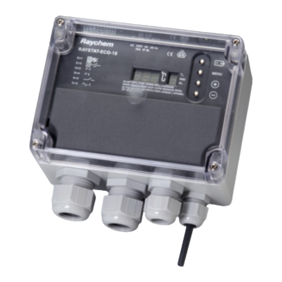
ENGLISH Table of contents ......................... Description & Technical data .....................1 Functional description .......................2 Display ..........................2 Installation description ......................3 Operational description .....................6 11 Testing, commissioning and maintenance ................9 14 Wiring diagrams ........................51 Commissioning sheet ......................53 DEUTSCH Inhaltsverzeichnis ....................... Beschreibung und technische Daten ................... 15 Funktionsbeschreibung ....................... - Página 5 ENGLISH A 1. Thermostat enclosure B 1. Terminal screwdriver 3 mm 2, 3, 4, 5. Cable entries 2. Posi-drive screwdriver 5 mm (2 x M25, 1 x M20, 1 x M16) 3. Trimming knife 6. Temperature sensor Pt 100 4, 5, 6. Spanners 7.
-
Página 6: Technical Data
DESCRIPTION RAYSTAT-ECO-10 is an electronic controller with display, advanced alarm facilities and the capability of switching large currents. The RAYSTAT-ECO-10 is designed to control heating cable systems. Heating cable can be controlled either directly by the RAYSTAT-ECO-10 or via a contactor. Direct switching of heating cables is possible for heating loads up to 25 A. -
Página 7: Functional Description
T sensor Type: 3-wire Pt 100 according to IEC Class B Sensor head: 50 mm x Ø 6 mm * An external Pt 100 sensor can be connected, the sensor cable can be extended with a 3-core shielded cable of 20 Ω max. per conductor (e.g. up to 150 m with a 3 x 1.5 mm²... -
Página 8: Installation Description
There are 4 different display modes possible: 1. In the normal operation mode (no error condition), the measured temperature or the set point temperature value are displayed in the value display (alternating). During the time that the actual measured temperatures is shown, the TA LED in the status display lights up. - Página 9 2. Mounting of the enclosure The RAYSTAT-ECO-10 can be installed indoor or outdoor. Do not install the thermostat under the thermal insulation. Wall mounting Mount the enclosure using wall fasteners (screws) via the four, 4 mm Ø holes. Mounting on a pipe Thermal Management offers different support brackets (not included) to mount the RAYSTAT-ECO-10 on a pipe: SB-100 or SB-101.
-
Página 10: Complete Installation
4. Installation of the sensor Location of the sensor Mount the sensor in a position exposed to normal weather conditions but shielded from direct sunlight. The sensor should not be located against surfaces that are heated from within or may be heated by sunlight. If the RAYSTAT-ECO-10 is located outdoors, the sensor cable may be shatened and the sensor may be mounted directly to the bottom of the housing, but make sure that at least 35 - 40 mm of the sensor extends beyond the... -
Página 11: Operational Description
OPERATIONAL DESCRIPTION 1. Introduction The RAYSTAT-ECO-10 parameters are configured via a menu system. The unit is delivered with a battery so that the operating parameters can be set up without any need for the power supply to be connected. This is useful for setting units on the bench prior to mounting in their working location or on site when power isn’t available. - Página 12 3. Parameters The first parameter to show up during Set-up mode is the Set Point. Other parameters, their default, minimum and maximum values are shown in the below table: Default Displayed Parameter Min. Max. value Code Set Point (°C) Min. Expected Ambient (°C) Pipe Size Heater Operation if Sensor Error...
-
Página 14: Testing, Commissioning And Maintenance
TESTING, COMMISSIONING AND MAINTENANCE Test heating cable when thermostat installation is complete as directed in the instructions applicable for the heating cable. Fill out the commisioning sheet (page 3514). Maintain thermostat during normal plant maintenance. Check: • Mounting is firm • Exposed sensor cable is not damaged • Glands are tightened firmly • Thermostat operation is correct (no error code displayed) -
Página 15: Technische Daten
BESCHREIBUNG Das elektronische Steuergerät RAYSTAT-ECO-10 ist mit einem digitalen Display und umfassenden Alarmfunktionen ausgestattet. Es wurde speziell für die Begleitheizsysteme entwickelt und ist für hohe Belastungen ausgelegt. Das Heizband kann entweder direkt über das Steuergerät oder einen Leistungsschütz geschaltet werden. Bei einem Schaltstrom von max. 25 A ist eine Schaltung über den Thermostaten zu empfehlen. -
Página 16: Funktionsbeschreibung
Gehäuse Umgebungstemperatur- bereich: –40°C bis +80°C Schutzart: IP65 Bohrungen: 2 x M25, 1 x M20, 1 x M16 Abmessungen: 120 x 160 x 90 mm Gewicht: ca. 800 g Material: Graues Polycarbonat Deckelbefestigung: 4 x M6, Zylinderkpfschrauben - rostfreier Stahl Montage: Wandmontage oder auf Befestigungswinkel SB-100/SB-101... -
Página 17: Display
Bei einer Störung schaltet das Alarmrelais, und in der Anzeige erscheint eine Fehlermeldung. Sie können außerdem eingeben, ob das Begleitheizsystem bei einem Sensorausfall abschalten oder weiter in Betrieb bleiben soll (EIN oder AUS). Das Steuergerät ist zusätzlich mit einer Batterie (im Lieferumfang) ausgestattet, so dass die Programmierung auch ohne Netzspannungsanschluss vorgenommen werden kann (siehe „Programmierung“... -
Página 18: Montage
MONTAGE 1. Heizbandmontage Informationen zur Auswahl und Auslegung von Frostschutzsystemen in der Bautechnik finden Sie in unserem Technischen Handbuch. Eine detaillierte Auswahlhilfe für industrielle Begleitheizsysteme von Thermal Management finden Sie in unserer Projektierungsanleitung für industrielle Begleitheizsysteme, bzw. in unserer speziell entwickelten Planungssoftware „TraceCalc“. - Página 19 Heizbandanschluss Das Heizband kann über einen Anschlußkasten, ein Leistungsschütz oder RayClic mit dem Kaltende des Anschlußmoduls direkt durch die M25-Verschraubung 3 angeschlossen werden. Das Heizband kann auch direkt im Steuergerät angeschlossen werden. In diesem Fall muss die M25-Verschraubung 3 , die bei der Lieferung bereits am Steuergerät montiert ist, durch eine entsprechende Anschlussgarnitur ersetzt werden (siehe Tabelle S.
-
Página 20: Programmierung
5. Fertigstellung der Montage Bringen Sie die Gehäuseabdeckung wieder an. Wenn Sie das Steuergerät RAYSTAT-ECO-10 noch nicht programmiert haben, folgen Sie nun den Hinweisen im Kapitel „Programmierung“ auf Seite 20. Schließen Sie den Deckel des Gehäuses. FUNKTIONSBESCHREIBUNG 1. Einleitung Die RAYSTAT-ECO-10 Parameter sind über ein System-Menü einstellbar. Das Steuergerät ist zusätzlich mit einer Batterie ausgestattet, so dass die Programmierung auch ohne Netzspannungsanschluss erfolgen kann. - Página 21 Wenn das Steuergerät auf seine Werkseinstellungen zurückgesetzt werden soll, dann drücken Sie gleichzeitig die Tasten + und – für ca. 2 Sekunden. Im Display erscheint anschließend (Default). 3. Parameter Der erste angezeigte Parameter im Display während des Programmiermodus ist die Haltetemperatur. Andere Parameter, Werkseinstellungen, Minimum- und Maximumwerte können aus der folgenden Tabelle entnommen werden.
-
Página 23: Test, Inbetriebnahme Und Wartung
TEST, INBETRIEBNAHME UND WARTUNG Nachdem Sie das Steuergerät montiert haben, prüfen Sie, ob das Heizband ordnungsgemäß funktioniert. Hinweise zur Überprüfung finden Sie in der Montageanleitung des Heizbandes. Nun füllen Sie das Inbetriebnahmeprotokoll aus (Seite 35). Das Steuergerät sollte in regelmäßigen Abständen gewartet werden. Prüfen Sie, ob • das Steuergerät fest montiert ist • das Sensorkabel beschädigt wurde... -
Página 24: Caractéristiques Techniques
DESCRIPTION Le RAYSTAT-ECO-10 est un régulateur électronique avec un afficheur, des fonctions d’alarme avancées et la capacité de commuter des courants importants. Il est conçu pour réguler les systèmes de traçage électrique. Le ruban chauffant est commandé soit directement par le RAYSTAT- ECO-10 soit par le biais d’un contacteur. -
Página 25: Sonde De Température
Boîtier Température de service: –40°C à +80°C Protection: IP 65 Entrées: 2 x M25, 1 x M20, 1 x M16 Dimensions: 20 x 160 x 90 mm Poids approx.: 800 g Matériau: polycarbonate Montage: sur paroi ou support du fixation sur la tuyauterie SB-100 / SB-101 Sonde de température Type:... -
Página 26: Afficheur
En cas d’hésitation à propos du réglage adéquat, il vaut mieux choisir une valeur trop élevée que trop basse pour éviter tout risque de gel des conduites. En cas d’erreur, le relais d’alarme est sollicité et un code d’erreur est donné... -
Página 27: Installation
INSTALLATION 1. Pose du ruban chauffant Pour l’étude et la sélection des rubans chauffants dans les applications bâtiment, voir le Manuel Technique. Pour les rubans chauffants destinés à l’industrie, voir le Guide de sélection industrie, utiliser la dernière version du logiciel TraceCalc ou encore prendre contact avec votre agent Thermal Management. -
Página 28: Installation De La Sonde
3. Câblage Ôter le capot du terminal pour accéder aux bornes de connexion. Alimentation: Faire passer un câble monophasé (230 Vca) dans le presse-étoupe 2 , taille M25 (schéma A ) et raccorder selon le schéma électrique de la page 37. Raccordement du ruban chauffant: Via une boîte de jonction ou un contacteur, ou en utilisant RayClic, avec le câble froid dans le presse-étoupe 3 (M25). -
Página 29: Fin De L'iNstallation
Remarque: le câble de la sonde peut être prolongé jusqu’à 150 m avec un câble de section 3 x 1,5 mm2. Raccorder cette prolongation dans une boîte de jonction JB-86 ou dispositif équivalent. Utiliser un câble blindé pour éviter les interférences. La tresse de blindage doit être reliée à la prise de terre du régulateur. -
Página 30: Paramètres
Pour mettre le thermostat en mode de paramétrage lorsque l’appareil est raccordé à l’alimentation électrique (l’afficheur indique alternativement le point de consigne et la valeur de température mesurée), appuyer sur la touche MENU pendant 2 secondes environ. Parcourir la liste complète des paramètres effectués en appuyant successivement sur la touche Menu. -
Página 32: Test, Mise En Service Et Entretien
TEST, MISE EN SERVICE ET ENTRETIEN Procéder à l’essai du ruban chauffant à la fin de l’installation du régulateur conformément aux instructions de Thermal Management concernant le ruban chauffant. Compléter la fiche de mise en service (page 35). Vérifier et entretenir le régulateur lors de la maintenance régulière des installations. -
Página 33: Dati Tecnici
DESCRIZIONE RAYSTAT-ECO-10 è un controllore elettronico dotato di display, funzioni di allarme avanzate e la capacità di commutare correnti elevate. RAYSTAT-ECO-10 è progettato per controllare sistemi di tracciatura elettrica. I cavi scaldanti possono essere controllati direttamente dall’unità RAYSTAT- ECO-10 o attraverso un contattore. La commutazione diretta dei cavi scaldanti è... -
Página 34: Sensore Di Temperatura
Sensore di temperatura Tipo: Pt 100 a 3 fili, conforme alla norma IEC Classe B Testa del sensore: 50 mm x Ø 6 mm * È possibile collegare un sensore Pt 100 esterno; il cavo del sensore può essere prolungato con un cavo schermato a 3 conduttori da 20 Ω max. per conduttore (es. -
Página 35: Procedura Di Installazione
Il display può operare in quattro modalità: 1. In modalità di funzionamento normale (senza condizioni di errore), la parte sinistra del display mostra a fasi alterne la temperatura misurata e il setpoint. Quando è visualizzata la temperatura misurata, nella parte destra del display si accende il LED TA. - Página 36 2. Montaggio dell’involucro L’unità RAYSTAT-ECO-10 può essere installata in ambienti chiusi o all’aperto. Non installare il termostato sotto l’isolamento termico. Montaggio a parete Montare l’involucro mediante tasselli (a vite) usando i quattro fori con Ø 4 mm. Installazione su tubazioni Thermal Management offre diverse staffe di supporto (non incluse) per l’installazione dell’unità...
-
Página 37: Installazione Del Sensore
4. Installazione del sensore Posizione del sensore Installare il sensore in una posizione esposta a condizioni atmosferiche normali ma al riparo dalla luce diretta del sole. Il sensore non deve essere collocato contro superfici che siano riscaldate dall’interno o che possano essere riscaldate dalla luce solare. -
Página 38: Descrizione Operativa
DESCRIZIONE OPERATIVA 1. Introduzione I parametri dell’unità RAYSTAT-ECO-10 devono essere configurati attraverso un sistema a menu. Il dispositivo è provvisto di una batteria interna, che consente di configurare i parametri operativi senza bisogno di collegare l’unità all’alimentazione elettrica. Questo è particolarmente utile per configurare le unità... - Página 39 3. Parametri Il primo parametro che compare quando si attiva la modalità di configurazione è il setpoint. La tabella qui sotto mostra gli altri parametri, i rispettivi valori predefiniti e le impostazioni minime e massime consentite: Valore Codice Parametro Min. Max.
-
Página 41: Collaudo, Messa In Servizio E Manutenzione
COLLAUDO, MESSA IN SERVIZIO E MANUTENZIONE Dopo l’installazione del termostato, collaudare il cavo scaldante come descritto nelle istruzioni del prodotto. Compilare la scheda di messa in servizio (pag. 3541). Eseguire la manutenzione del termostato durante la normale manutenzione dell’impianto. Controllare: • La solidità... -
Página 42: Descripción
DESCRIPCIÓN RAYSTAT-ECO-10 es un controlador electrónico con pantalla digital, de prestaciones avanzadas, con alarmas y capacidad de corte para altas intensidades. El RAYSTAT-ECO-10 se ha diseñado para controlar sistemas de cables calefactores (traceado eléctrico). El cable calefactor puede controlarse directamente con el RAYSTAT-ECO-10 (corte directo) o mediante un contactor de potencia. -
Página 43: Descripción Funcional
Sensor Tª Tipo: PT 100 de 3 hilos conforme con IEC Clase B Cabezal del sensor: 50 mm x Ø 6 mm * Puede conectarse un sensor externo PT 100; el cable del sensor puede extenderse con un cable apantallado de 3 conductores de 20 Ω como máx. por conductor (Ej.: hasta 150 m cable de 3 x 1,5 mm²) DESCRIPCIÓN FUNCIONAL El controlador Raystat-ECO-10 se utiliza para controlar sistemas de traceado... -
Página 44: Descripción De La Instalación
Existen 4 posibles modos de pantalla diferentes: 1. En el modo normal de operación (sin errores), en el indicador de valor aparece el valor de la temperatura medida o el de la temperatura de punto de consigna (alternativamente). Durante el tiempo en que se muestran las temperaturas reales medidas, el LED TA del indicador de estado se ilumina. -
Página 45: Montaje De La Envolvente
2. Montaje de la envolvente El RAYSTAT-ECO-10 puede instalarse en interior o intemperie. No instale el termostato debajo del aislamiento térmico. Montaje en pared Monte la caja con fijaciones de pared (tornillos) en los cuatro orificios de 4 mm Ø. Montaje en una tubería Thermal Management ofrece distintos soportes (no incluidos con la unidad) para montar el RAYSTAT-ECO-10 en una tubería: SB-100 o SB-101. -
Página 46: Instalación Del Sensor
4. Instalación del sensor Ubicación del sensor Monte el sensor en una posición expuesta a las condiciones atmosféricas normales, pero protegido de la luz solar directa u otras influencias térmicas externas. El sensor no debería ubicarse en el lado opuesto de superficies que se calienten desde el interior o que caliente el sol. -
Página 47: Descripción Operativa
DESCRIPCIÓN OPERATIVA 1. Introducción Los parámetros del RAYSTAT-ECO-10 se configuran mediante un sistema de menús. La unidad se entrega con una batería, de forma que los parámetros operativos puedan configurarse sin necesidad de conectarse a la red eléctrica. Esto es útil para configurar unidades en el taller antes de montarlas en su ubicación definitiva o en algún lugar donde no haya suministro eléctrico. -
Página 48: Parámetros
3. Parámetros El primer parámetro que aparece durante el modo de configuración es el punto de consigna (S.P.). Los restantes parámetros, sus valores predeterminados, mínimo y máximo, se aprecian en la tabla siguiente: Valor Código Parámetro predeter- Mín. Máx. mostrado minado Punto de Consigna (°C) Ambiente mín. -
Página 50: Ensayos, Puesta En Marcha Y Mantenimiento
ENSAYOS, PUESTA EN MARCHA Y MANTENIMIENTO Pruebe el cable calefactor cuando se haya completado la instalación del termostato de conformidad con las instrucciones aplicables a dicho cable. Cumplimente la ficha de puesta en marcha (página 3550). Realice el mantenimiento del termostato durante el mantenimiento normal de la planta. -
Página 51: Esquemas De Conexionado
A. Wiring Diagrams Anschlussdiagramm Schémas électriques Schemi elettrici Esquema de conexionado Max. C 25 A 30 mA RAYSTAT-ECO-10 5 L L 8 N N A B C alarm* 2A max. R: Same colour R: die gleiche Farbe R: la même couleur R: Stesso colore D: Mismo color Heating cable... - Página 52 B. Voltage free operation: Remove links W1 and W2 and change “U” parameter in set up mode from “0” (not volt free) to “1” (volt free) as explained on page 12 of this manual. Potentialfreier Berieb: Entfermen Sie die Brücken W1 und W2 und ändern Sie die den Parameter für potentialfreien Betrieb “U”...
- Página 56 Fax +7 495 926 18 86 saleskz@pentair.com WWW.PENTAIRTHERMAL.COM Pentair is owned by Pentair or its global affiliates. All other trademarks are the property of their respective owners. Pentair reserves the right to change specifications without prior notice. © 2015-2017 Pentair.