AERMEC VEC Serie Manual De Uso
Ocultar thumbs
Ver también para VEC Serie:
- Manual de uso (24 páginas) ,
- Manual de instalacion y uso (50 páginas)
Tabla de contenido
Publicidad
Enlaces rápidos
M A N UA L E D ' U S O E I N S TA L L A Z I O N E
U S E A N D
MANUEL D'UTILISATION ET D'INSTALLATION
BEDIENUNGS- UND INSTALLATIONSHANDBUCH
M A N UA L D E U S O E I N S TA L A C I Ó N
VENTILCONVETTORE
FAN COIL
VENTILO-CONVECTEURS
GEBLÄSEKONVEKTOR
VEC
I N S TA L L AT I O N
IVECLJ 1712 - 5074550_05
M A N UA L
Publicidad
Tabla de contenido

Manuales relacionados para AERMEC VEC Serie


Resumen de contenidos para AERMEC VEC Serie
- Página 1 M A N UA L E D ’ U S O E I N S TA L L A Z I O N E U S E A N D I N S TA L L AT I O N M A N UA L MANUEL D'UTILISATION ET D'INSTALLATION BEDIENUNGS- UND INSTALLATIONSHANDBUCH...
-
Página 2: Observaciones
“DANGER” or “WARNING” AERMEC S.p.A. declines all liability for any damage due to because, if they are not complied with, the machine/property improper use of the machine, or the partial or superficial read- can damaged and/or people can be injured. -
Página 3: Index Certificat De Conformite
INDICE DICHIARAZIONE DI CONFORMITÀ Trasporto • Simboli di sicurezza Informazioni importanti • Manutenzione • Imballo • Utilizzo Descrizione dell'unità • Limiti di funzionamento Dati tecnici Installazione dell’unità • Collegamenti elettrici Accessori obbligatori Manutenzione (Sostituzione filtro) Dati dimensionali Schemi elettrici SOLUZIONE DEI PROBLEMI TABLE OF CONTENTS DECLARATION OF CONFORMITY Transport •... - Página 4 TRASPORTO • TRANSPORT • TRANSPORT • TRANSPORT • TRANSPORTE NICHT nass machen. NON bagnare. Tenere al KEEP DRY. Keep out of NE PAS mouiller. Tenir à NO mojar. Conservar pro- Vor Regen geschützt riparo dalla pioggia. the rain. l’abri de la pluie. tegido de la lluvia.
- Página 5 (specialmente se non si provvede a ven- superiori a 7 °C in estate. Aermec. tilare periodicamente la stanza, pulire il Una scelta oculata della temperatura filtro più spesso). ATTENZIONE: Si eviti che l'apparec- ambiente comporta risparmi energetici.
-
Página 6: Descrizione Dell'UNità
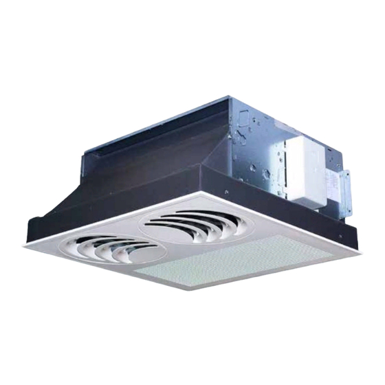
DESCRIZIONE DELL’UNITÀ Ventilconvettore per il trattamento dell’aria di un ambiente principalmente nella stagione estiva. L’unità si installa in controsoffitto. VERSIONI E GRANDEZZE DISPONIBILI I ventilconvettori della serie VEC sono disponibili in: 4 grandezze con batteria a 3 ranghi accessorio obbligatorio VEC 20 VEC 20 GL VEC 30... -
Página 7: Dati Tecnici
DATI TECNICI VEC con batteria a 3 ranghi VEC 20 VEC 30 VEC 40 VEC 50 Mod. Riscaldamento W (max.) 1835 2770 3745 4285 Potenza termica W (med.) 1505 2340 3105 3785 1105 1950 2505 2840 W (min.) Potenza termica resistenza elettrica W 1300 1650 1950... -
Página 8: Installazione Dell'UNita
INSTALLAZIONE ATTENZIONE: prima di effettuare degli impianti ed in grado di verificare sostanze acide od alcaline che possano qualsiasi intervento, assicurarsi che gli stessi ai fini della sicurezza e della danneggiare irrimediabilmente gli l’alimentazione elettrica sia disinserita. funzionalità. scambiatori di calore in rame-alluminio ATTENZIONE: prima di effettuare ATTENZIONE: Installare un dispositivo, o i componenti interni in plastica. -
Página 9: Extraordinary Cleaning
WARNING! DANGER! Any use of the CORRECTLY ADJUST THE AIR JET could be noises and creaks inside unit not expressly indicated by Aermec the device due to the various thermal Air coming out from the fan coil must is strictly prohibited. -
Página 10: Description Of The Unit
DESCRIPTION OF THE UNIT The fan coil is a room air treatment terminal unit for mainly summer operation. Install the unit on the suspended ceiling. AVAILABLE VERSIONS AND SIZES VEC fan coils are available in: 4 sizes with a 3-row coil compulsory accessory VEC 20 VEC 20 GL... -
Página 11: Technical Data
TECHNICAL DATA VEC with a 3-row coil VEC 20 VEC 30 VEC 40 VEC 50 Mod. Heating W (max.) 1835 2770 3745 4285 Heating capacity W (med.) 1505 2340 3105 3785 1105 1950 2505 2840 W (min.) Electric heater heating capacity 1300 1650 1950... -
Página 12: Installing The Unit
INSTALLATION WARNING: before carrying out any systems for the purposes of safety and irretrievably damage the aluminium- intervention, check the power supply is correct operation. copper heat exchanger or the internal disconnected. WARNING: install a device, main plastic parts. WARNING:before carrying out any switch or plug which allows to Do not install the unit in workshops or work, put the proper individual... - Página 13 INFORMATIONS IMPORTANTES SUR LA MAINTENANCE ATTENTION: le ventilo-convecteur est N E PA S U T I L I S E R L E V E N T I L O - vent. raccordé au réseau électrique et au CONVECTEUR DE FAÇON IMPROPRE Nettoyer fréquemment, retirer la pous- circuit hydraulique, une intervention sière accumulée avec un aspirateur.
-
Página 14: Limites De Fonctionnement
VERSIONS Ventilo-convecteur pour le traitement de l’air principalement en été. L’air est diffusé dans le milieu par des bouches qui, grâce à l'effet COANDA, font adhérer le jet d'air au plafond. L’unité s'installe au faux plafond. VERSIONS ET GRANDEURS DISPONIBLES Les ventilo-convecteurs de la série VEC sont disponibles en : 4 grandeurs avec batterie à... -
Página 15: Donnees Techniques
DONNEES TECHNIQUES avec batterie à 3 rangs Mod. VEC 20 VEC 30 VEC 40 VEC 50 Chauffage W (max.) 1835 2770 3745 4285 Puissance thermique W (moy.) 1505 2340 3105 3785 W (min.) 1105 1950 2505 2840 Puissance résistance électrique 1300 1650 1950... -
Página 16: Installation De L'UNité
INSTALLATION ATTENTION : s'assurer, avant d'effectuer transformation, le développement et inflammables ou des substances acides toute intervention, que l'alimentation l'entretien des installations, et en ou alcalines qui peuvent endommager électrique soit bien désactivée. mesure de vérifier ces derniers aux fins irrémédiablement les échangeurs de chaleur ATTENTION : Avant d'effectuer toute de la sécurité... -
Página 17: Wichtige Hinweise
Wohlbefinden der anwesenden Personen ACHTUNG ! GEFAHR! Jede ande- Beim Kühlbetrieb kann Wasserdampf gewährleistet ist, d.h. besonders wenn re nicht ausdrücklich von Aermec aus dem Vorlauf des Gebläsekonvektors es sich dabei um ältere Menschen, beschriebene Verwendung des Geräts ist austreten. -
Página 18: Beschreibung Der Einheit
BESCHREIBUNG DER EINHEIT Der Gebläsekonvektor ist eine Endeinheit für die Raumluftbehandlung sowohl für den Sommerbetrieb. Das Gerät wird in der Zwischendecke installiert. ERHÄLTLICHE AUSFÜHRUNGEN UND GRÖSSEN Die Gebläsekonvektoren der Baureihe VEC sind erhältlich in: 4 Größen mit 3-reihigem Wärmetauscher als obligatorisches Zubehör VEC 20 VEC 20 GL VEC 30... -
Página 19: Technische Daten
TECHNISCHE DATEN VEC mit 3-reihigem Wärmetauscher VEC 20 VEC 30 VEC 40 VEC 50 Mod. Heizbetrieb W (max.) 1835 2770 3745 4285 Heizleistung W (med.) 1505 2340 3105 3785 1105 1950 2505 2840 W (min.) Heizleistung des elektrischen Widerstands 1300 1650 1950 Kühlbetrieb... -
Página 20: Installation Der Einheit
INSTALLATION ACHTUNG: Stellen Sie vor jedem diese hinsichtlich der Sicherheit und sind, die zu einer unwiderruflichen Eingriff sicher, dass die Stromversorgung Funktionsfähigkeit zu prüfen. Beschädigung der Kupfer-/Aluminium- abgeschaltet ist. ACHTUNG: Installieren Sie eine W ä r m e a u s t a u s ch e r b z w. i n n e r e r A C H T U N G : S o r g e n S i e v o r... -
Página 21: Informaciones Importantes
Aermec. mucha energía. Es posible que el fan coil emita a veces ANOMALÍAS DE FUNCIONAMIENTO... -
Página 22: Descripción De La Unidad
DESCRIPCIÓN DE LA UNIDAD El fan coil es un terminal para el tratamiento del aire de un ambiente principalmente en verano. La unidad se instala en el falso techo. VERSIONES Y TAMAÑOS DISPONIBLES Los fan coils de la serie VEC están disponibles en: 4 tamaños con batería de 3 rangos accesorio obligatorio VEC 20... -
Página 23: Datos Técnicos
DATOS TÉCNICOS VEC con batería de 3 rangos VEC 20 VEC 30 VEC 40 VEC 50 Mod. Calentamiento W (máx.) 1835 2770 3745 4285 Potencia térmica W (med.) 1505 2340 3105 3785 1105 1950 2505 2840 W (mín.) Potencia térmica resistencia eléctrica W 1300 1650 1950... -
Página 24: Instalación De La Unidad
INSTALACIÓN AT E N C I Ó N : a n t e s d e c u a l q u i e r verificar la seguridad y la funcionalidad puedan dañar irremediablemente los intervención, asegúrese de que el de las mismas. -
Página 25: Accessori Obbligatori Mandatory Accessory Accessoire Obligatoire Obligatorischen Zubehörs Accesorio Obligatorio
ACCESSORI OBBLIGATORI MANDATORY ACCESSORY VEC20GL ACCESSOIRE OBLIGATOIRE OBLIGATORISCHEN ZUBEHÖRS ACCESORIO OBLIGATORIO 1185 VEC20GL VEC30GL VEC40GL VEC_GL VEC_G L VEC_GL Mit VEC_GL VEC_GL consente 2 a l lows 2 permet 2 sind 2 permite 2 posizioni di installa- installation positions: positions d'installation: Installationspositionen posiciones de instala- zione:... - Página 26 Installazione "A" Installazione "B" Installation "A" Installation "B" Instalación "A" Instalación "B" IVECLJ 1712 - 5074550_05...
- Página 27 INSTALLAZIONE E SOSTITUZIONE DEL FILTRO ARIA INSTALLATION AND REPLACEMENT OF THE AIR FILTER INSTALLATION ET REMPLACEMENT DU FILTRE A AIR INSTALLATION UND AUSTAUCH DES LUFTFILTERS INSTALACIÓN Y SUSTITUCIÓN DEL FILTRO DE AIRE IVECLJ 1712 - 5074550_05...
-
Página 28: Dimensioni [Mm] Dimensions [Mm] Données Des Les Dimensions [Mm] Abmessungen Datos [Mm] Dimensionales [Mm]
DIMENSIONI [mm] DIMENSIONS [mm] DONNÉES DES LES DIMENSIONS [mm] ABMESSUNGEN DATOS [mm] DIMENSIONALES [mm] 284(A) / 314(B) [mm] [mm] Peso • Weight • Poids • Gewicht • Peso (VEC) [kg] 15,5 20,6 24,7 24,7 Peso • Weight • Poids • Gewicht • Peso (VEC GL) [kg] IVECLJ 1712 - 5074550_05... - Página 29 SCHEMI ELETTRICI • WIRING DIAGRAMS • SCHEMAS ELECTRIQUES • SCHALTPLÄNE • ESQUEMAS ELÉCTRICOS LEGENDA • READING KEY • LEGENDE • LEGENDE • LEYENDA = Fusibile • Fuse • Fusible SPC = Dispositivo scarico condensa AR = Arancio • Orange • Orange • Orange • Naranja Sicherung •...
- Página 30 SCHEMI ELETTRICI • WIRING DIAGRAMS • SCHEMAS ELECTRIQUES • SCHALTPLÄNE • ESQUEMAS ELÉCTRICOS Gli schemi elettrici sono soggetti ad un continuo aggiornamento, è obbligatorio quindi fare riferimento a quelli a bordo macchina. A l l w i r i n g d i a g r a m s a r e c o n s t a n t l y...
- Página 31 SCHEMI ELETTRICI • WIRING DIAGRAMS • SCHEMAS ELECTRIQUES • SCHALTPLÄNE • ESQUEMAS ELÉCTRICOS PXAE + VC + VF 4 tubi pannello PXAE a muro 4 tubes PXAE wall-mounted panel 4 tuyaux panneau PXAE inst. murale 4 Röhren Platte PXAE an Wand 4 tubos panel PXAE mural PXAE + VCF 2 tubi pannello PXAE a muro...
- Página 32 SCHEMI ELETTRICI • WIRING DIAGRAMS • SCHEMAS ELECTRIQUES • SCHALTPLÄNE • ESQUEMAS ELÉCTRICOS PXAR + VF + RX 2 tubi pannello PXAR a muro 2 tubes PXAR wall-mounted panel 2 tuyaux panneau PXAR inst. murale 2 Röhren Platte PXAR an Wand 2 tubos panel PXAR mural Gli schemi elettrici sono soggetti ad un continuo aggiornamento, è...
- Página 33 SCHEMI ELETTRICI • WIRING DIAGRAMS • SCHEMAS ELECTRIQUES • SCHALTPLÄNE • ESQUEMAS ELÉCTRICOS KTLP + VCF KTLP + VC + VF 2 tubi 4 tubi 2 tube 4 tube 2 tuyaux 4 tuyaux 2 Röhren 4 Röhren 2 tubos 4 tubos WMT05 2 tubi 2 tube...
- Página 34 SCHEMI ELETTRICI • WIRING DIAGRAMS • SCHEMAS ELECTRIQUES • SCHALTPLÄNE • ESQUEMAS ELÉCTRICOS WMT10 + VCF 2 tubi 2 tube 2 tuyaux 2 Röhren 2 tubos WMT10 + VF + VC 4 tubi 4 tube 4 tuyaux 4 Röhren 4 tubos WMT10 + VF + RX 2 tubi 2 tube...
- Página 35 SCHEMI ELETTRICI • WIRING DIAGRAMS • SCHEMAS ELECTRIQUES • SCHALTPLÄNE • ESQUEMAS ELÉCTRICOS FMT10 + VCF 2 tubi 2 tube 2 tuyaux 2 Röhren 2 tubos FMT10 + VF + VC 4 tubi 4 tube 4 tuyaux 4 Röhren 4 tubos FMT10 + VF + RX 2 tubi 2 tube...
- Página 36 SCHEMI ELETTRICI • WIRING DIAGRAMS • SCHEMAS ELECTRIQUES • SCHALTPLÄNE • ESQUEMAS ELÉCTRICOS FMT20 + VCF 2 tubi 2 tube 2 tuyaux 2 Röhren 2 tubos FMT20 + VF + VC 4 tubi 4 tube 4 tuyaux 4 Röhren 4 tubos FMT20 + VF + RX 2 tubi 2 tube...
- Página 37 SCHEMI ELETTRICI • WIRING DIAGRAMS • SCHEMAS ELECTRIQUES • SCHALTPLÄNE • ESQUEMAS ELÉCTRICOS PXAE SIT3 + SIT5 OUTPUT INPUT OUTPUT INPUT OUTPUT INPUT Gli schemi elettrici sono soggetti ad un continuo aggiornamento, è obbligatorio quindi fare riferimento a quelli a bordo macchina. A l l w i r i n g d i a g r a m s...
- Página 38 SOLUZIONE DEI PROBLEMI • SOLUTION DES PROBLEMES PROBLEMA • PROBLEM PROBABILE CAUSA • PROBABLE CAUSE SOLUZIONE • REMEDY PROBLEME • PROBLEM CAUSE PROBABLE • MÖGLICHE URSACHE SOLUTION • ABHILFE PROBLEMA CAUSA PROBABLE SOLUCIÓN Poca aria in uscita. Errata impostazione della velocità sul pannello comandi. Scegliere la velocità...
- Página 39 DATI IN ACCORDO CON IL REGOLAMENTO EU 2016/2281 • DATA IN ACCORDANCE WITH EU REGULATION 2016/2281 • DONNÉES SELON LA RÉGLE- MENTATION DE L’UE 2016/2281 • DATEN GEMÄSS EU 2016/2281-VERORDNUNG • DATOS SEGÚN LA REGULACIÓN DE LA UE 2016/2281 IMPIANTO A DUE TUBI - TWO-PIPE-SYSTEM - SYSTÈME À DEUX TUYAUX - ZWEI-ROHR-SYSTEM - SISTEMADE TUBO DOS: Taglie - size - Tailles - Größen - Tamaños (1) Impostazione velocità...
-
Página 40: Salida De Servicio Y Eliminación De Los Componentes De La Máquina
AERMEC S.p.A. si riserva la facoltà di apportare in qualsiasi momento tutte le modifiche ritenute necessarie per il miglioramento del prodotto. Les données mentionnées dans ce manuel ne constituent aucun engagement de notre part. Aermec S.p.A. se réserve le droit de modifier à tous moments les données considérées nécessaires à...