Publicidad
Idiomas disponibles
Idiomas disponibles
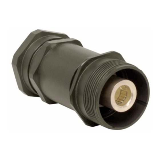
Roughneck™ (non-EX)
multi-pin connector
Installation & maintenance information
SAVE THESE INSTRUCTIONS FOR FUTURE REFERENCE
WARNING
SHOCK HAZARD
To avoid electrical shock or electrocution, if any parts of the
plug or receptacle appear to be missing, broken or show
signs of damage, DISCONTINUE USE IMMEDIATELY.
Replace with the proper replacement part(s) before
continuing service.
WARNING
SHOCK HAZARD
To avoid electrical shock or electrocution, electrical power
supply must be OFF before and during installation and
maintenance. Installation and maintenance procedure must
be performed by a trained and competent electrician.
Note:
For use with stranded copper wire.
Reference Section 9 for maximum heat dissipation calculation, prior to installation.
To be sold with Installation Instructions.
Section 1: Installation Instructions for Multi-pin Male Plugs
9. Mechanical Clamp
8.Basket
Weave
1. Cable Adapter
7. Bushing
A. To disassemble male plug:
1.
Place cable adapter body (1) in rubber or aluminum
jawed vice. Unscrew male skirt (2) (left hand thread)
from cable adapter (1), keeping environmental cover (3)
on male skirt (2).
2.
Remove cable adapter body (1) from vice and place male
skirt (2) in vice, clamping onto environmental cover (3)
with warning label facing down.
3.
Unscrew coupling nut (4) from environmental cover (3).
B. To connect cable to male plug:
1.
Thread cable through mechanical clamp (9) or
basketweave (8), bushing (7) then cable adapter (1) then
coupling nut (4). Allow to rest down cable out of way.
2.
Prepare cable and individual conductors following
directions from Section 6.
3.
Terminate conductors onto pins per Section 6.
4.
Confirm resilient insert (6) (red) is firmly in place within
the male skirt (2).
5.
Locate pin location 1 on the insert and press desired
pin into insert. Follow pin insertion instructions from
Section 7 .
6.
Continue to populate remaining pin locations on insert
with pins. WARNING: ALL INSERT LOCATIONS MUST
BE FULLY POPULATED WITH PINS.
IF 1688 • 08/18
Copyright © 2018 Eaton's Crouse-Hinds Division
WARNING
SHOCK HAZARD
To avoid electrical shock or electrocution, connectors with
male pins must not be used as the power source, as the
user may come in contact with energized contacts or other
components.
6. Resilient Insert
4. Coupling Nut
3. Environmental
2. Male Skirt
Cover
C. To re-assemble male plug:
1.
Thread coupling nut (4) onto environmental cover
(3).
2.
Thread cable adapter (1) (left hand thread) onto
male skirt (2) and tighten to torque value found
on Table 3. Verify male skirt (2) is wrenched fully
to the shoulder of the cable adapter (1) to ensure
environmental integrity.
3.
Screw basketweave (8) or mechanical clamp (9)
onto the end of the cable adapter (1). Screw it
down tight enough to squeeze the busing firmly
against the cable. While doing this, push in on the
cable to prevent strain on the wire terminals.
4.
Fully tighten with wrench.
5.
If using mechanical clamp, tighten cord grip screws
to torque found on Table 3.
Section 2: Installation Instructions for Multi-pin Female Inline and Square Flange
IF 1688
9. Mechanical Clamp
8.Basket
Weave
7. Bushing
A. To disassemble female inline receptacle:
1.
Place cable adapter (1) in rubber or aluminum jawed vice.
Unscrew female skirt (2) (left hand thread) from cable
adapter (1), keeping environmental cover (3) on female
skirt (2).
2.
Remove cable adapter (1) from vice and place female skirt
(2) in vice, clamping onto environmental cover (3) with
warning label facing down.
B. To connect cable to female inline receptacle:
1.
Thread cable through mechanical clamp (9) or basketweave
(8), bushing (7) and cable adapter (1). Allow to rest down
the cable out of way.
2.
Prepare cable and individual conductors following
directions from Section 6.
3.
Terminate conductors onto pins per Section 6.
4.
Confirm resilient insert (6) (green) is firmly in place.
5.
Locate pin location 1 on the insert and press desired
pin into insert. Follow pin insertion instructions from
Section 7 .
Section 3: Installation Instructions for Panel Mount Receptacle
1. Insert Clamp Nut
A. To disassemble female panel mount receptacle:
1.
Place female square flange skirt (2) in rubber or
aluminum jawed vice with top of environmental cover
(3) facing the floor. Unscrew insert clamp nut (1) (left
hand thread) from female square flange skirt (2), keeping
environmental cover (3) on female square flange skirt (2).
B. To connect cable to panel mount receptacle:
1.
Thread cable through insert clamp nut (1) and allow to
rest further down on the cable out of the way.
2.
If using multi-conductor cable, refer to Section 2 (step
B2-B6) for cable installation process. If using single
conductor cable, refer to Section 4 (step B2-B5) for male
contact and Section 5 (step B2-B6) for female contact
installation process.
Page 1
IF 1688 • 08/18
Receptacle
2. Female
3. Environmental
Cover
Skirt
1. Cable Adapter
6.
Continue to populate remaining pin
locations on insert with pins. WARNING: ALL INSERT
LOCATIONS MUST BE FULLY POPULATED WITH
PINS.
C. To re-assemble female inline receptacle:
1.
Thread cable adapter (1) (left hand thread) onto female
skirt (2) and tighten to torque value found in Table 3.
Verify female skirt (2) is wrenched fully to the shoulder
of cable adapter (1) to ensure environmental integrity.
2.
Torque mechanical clamp (9) or basketweave (8) to
cable adapter (1) per torque value found in Table 3.
3.
Screw basketweave (8) or mechanical clamp (9) onto
the end of the cable adapter (1). Screw it down tight
enough to squeeze the bushing firmly against the
cable. While doing this, push in on the cable to prevent
strain on the wire terminals.
4.
Fully tighten with wrench.
5.
If using mechanical clamp, tighten cord grip screws to
torque found on Table 3.
2. Female Square
3. Environmental Cover
Flange Skirt
C. To re-assemble female panel mount receptacle:
1.
Thread insert clamp nut (1) (left hand thread) onto
square flange skirt (2) and tighten to torque value found
on Table 3. Verify female square flange skirt (2) is
wrenched fully to the shoulder of insert clamp nut (1) to
ensure environmental integrity.
Copyright © 2018 Eaton's Crouse-Hinds Division
6. Resilient Insert
Page 2
Publicidad
Tabla de contenido

Manuales relacionados para Eaton Roughneck


Resumen de contenidos para Eaton Roughneck
- Página 1 Continue to populate remaining pin locations on insert with pins. WARNING: ALL INSERT LOCATIONS MUST BE FULLY POPULATED WITH PINS. IF 1688 • 08/18 Copyright © 2018 Eaton’s Crouse-Hinds Division Page 1 IF 1688 • 08/18 Copyright © 2018 Eaton’s Crouse-Hinds Division...
- Página 2 Repeat steps 5-8 for each wire and contact as required. IF 1688 • 08/18 Copyright © 2018 Eaton’s Crouse-Hinds Division Page 3 IF 1688 • 08/18 Copyright © 2018 Eaton’s Crouse-Hinds Division...
- Página 3 313 MCM 1.85 44.45 444 MCM 1.85 44.45 535 MCM 1.85 44.45 777 MCM 1.85 44.45 IF 1688 • 08/18 Copyright © 2018 Eaton’s Crouse-Hinds Division Page 5 IF 1688 • 08/18 Copyright © 2018 Eaton’s Crouse-Hinds Division Page 6...
- Página 4 All statements, technical information and recommendations contained herein are based on information and tests we believe to be reliable. The accuracy or completeness thereof are not guaranteed. In accordance with Eaton’s Crouse-Hinds Division’s “Terms and Conditions of Sale,” and since conditions of use are outside our control, the purchaser should determine the suitability of the product for his intended use and assumes all risk and liability whatsoever in connection therewith.
-
Página 5: Roughneck™ Conector De Clavijas Múltiples (De Tipo No Ex) Información De Mantenimiento E Instalación
B2-B5) para el proceso de instalación del contacto macho y sección 5 (paso B2-B6) para el proceso de instalación del contacto hembra. IF 1688 • 08/18 Copyright © 2018 Eaton’s Crouse-Hinds Division Página 1 IF 1688 • 08/18 Copyright © 2018 Eaton’s Crouse-Hinds Division... - Página 6 Repita los pasos 5-8 para cada cable y contacto según sea necesario. IF 1688 • 08/18 Copyright © 2018 Eaton’s Crouse-Hinds Division Página 3 IF 1688 • 08/18 Copyright © 2018 Eaton’s Crouse-Hinds Division...
-
Página 7: Sección 10: Tabla De Referencias
313 MCM 1,85 44,45 444 MCM 1,85 44,45 535 MCM 1,85 44,45 777 MCM 1,85 44,45 IF 1688 • 08/18 Copyright © 2018 Eaton’s Crouse-Hinds Division Página 5 IF 1688 • 08/18 Copyright © 2018 Eaton’s Crouse-Hinds Division Página 6... -
Página 8: Longitud De La Camisa Desprovista (Cable De Conductores Múltiples)
Eaton’s Crouse-Hinds Division IF 1688 1201 Wolf Street, Syracuse, NY 13208 Revisión 4 Copyright © 2018 Revised 08/18 IF 1688 • 08/18 Copyright © 2018 Eaton’s Crouse-Hinds Division Página 7 Supercedes 05/15... - Página 9 Reportez-vous aux son étanchéité. instructions décrivant l’insertion des broches à la section 7. IF 1688 • 08/18 Tous droits réservés © 2018, Eaton’s Crouse-Hinds Division Page 1 IF 1688 • 08/18 Tous droits réservés © 2018, Eaton’s Crouse-Hinds Division...
- Página 10 Répétez les étapes 5 à 8 pour chaque conducteur et chaque contact. IF 1688 • 08/18 Tous droits réservés © 2018, Eaton’s Crouse-Hinds Division Page 3 IF 1688 • 08/18 Tous droits réservés © 2018, Eaton’s Crouse-Hinds Division...
- Página 11 444 MCM 1,85 44,45 535 MCM 1,85 44,45 777 MCM 1,85 44,45 IF 1688 • 08/18 Tous droits réservés © 2018, Eaton’s Crouse-Hinds Division Page 5 IF 1688 • 08/18 Tous droits réservés © 2018, Eaton’s Crouse-Hinds Division Page 6...
- Página 12 à l’usage qu’il prévoit en faire et assume tous les risques et toutes les responsabilités à cet égard. Eaton’s Crouse-Hinds Division IF 1688 1201 Wolf Street, Syracuse, NY 13208 Révision 4 Tous droits réservés © 2018 Revised 08/18 IF 1688 • 08/18 Tous droits réservés © 2018, Eaton’s Crouse-Hinds Division Page 7 Supersedes 05/15...